Liquid-cooled charging equipment with multiple charging connector assemblies and method of operating the same

Pending Publication Date: 2022-07-14
DELTA ELECTRONICS INC
View PDF0 Cites 1 Cited by
  • Summary
  • Abstract
  • Description
  • Claims
  • Application Information

AI Technical Summary

Benefits of technology

[0014]Accordingly, the method of operating the liquid-cooled charging equipment with multiple charging connector assemblies is provided to determine whether the pipe is in the coolant leakage or whether the charging connector is in the overheat by using the pressure sensor, the flow sensor, and the temperature sensor so that the early warning, protection, and maintenance can be taken i

Problems solved by technology

However, the larger output power may cause the charging cable to generate high heat due to the larger current during the charging process.
Therefore, as long as one of the charging connector assemblies is abnormal, the remaining charging connector assemblies will not be able to continue to operate due to th

Method used


Image

  • Liquid-cooled charging equipment with multiple charging connector assemblies and method of operating the same
  • Liquid-cooled charging equipment with multiple charging connector assemblies and method of operating the same
  • Liquid-cooled charging equipment with multiple charging connector assemblies and method of operating the same

Examples


first embodiment

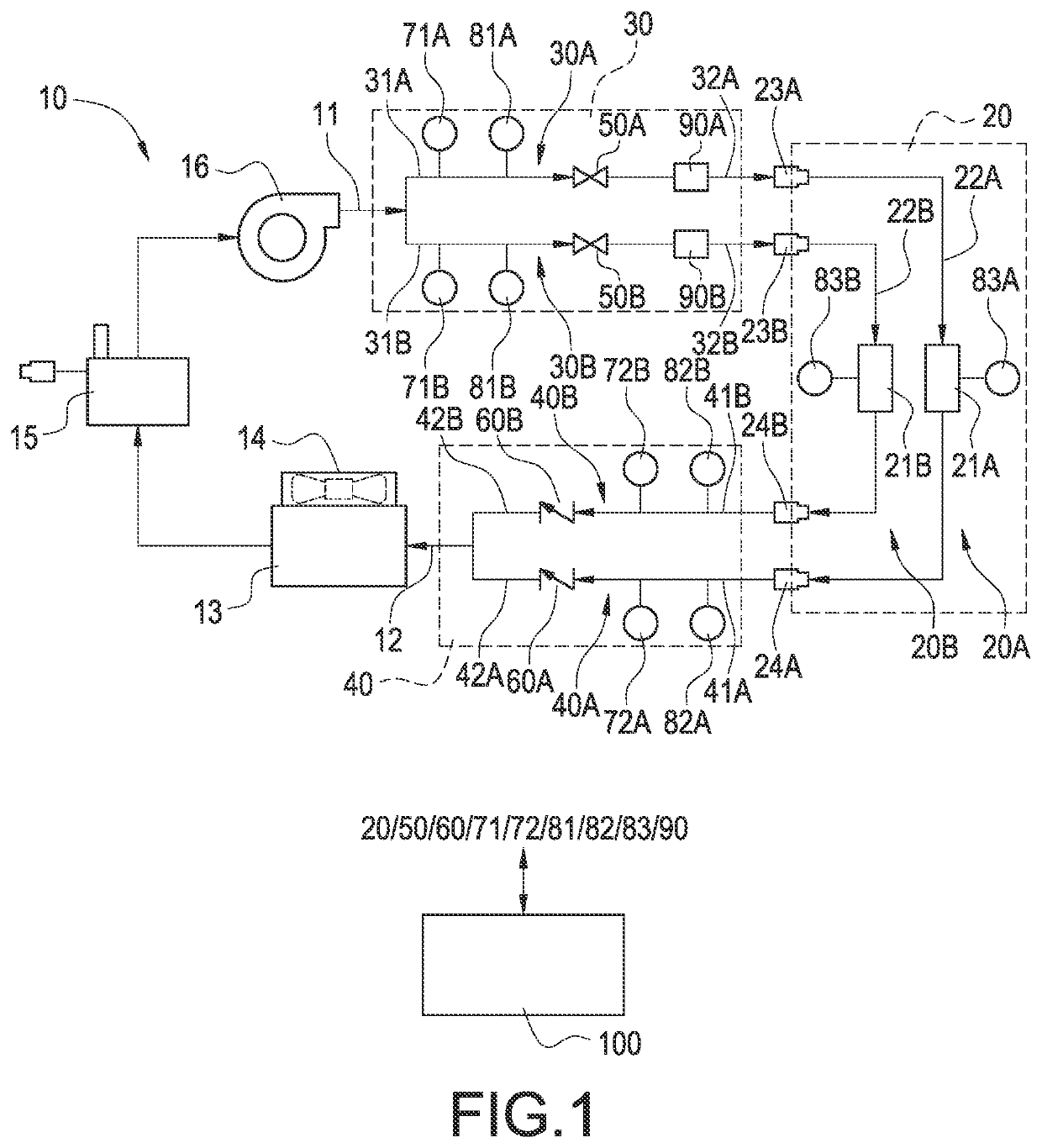
[0038]Please refer to FIG. 2, which shows a schematic diagram of the liquid-cooled charging equipment with multiple charging connector assemblies operating in a normal condition according to the present disclosure. After the charging connector assembly of the liquid-cooled charging equipment is connected to the electric vehicle, the controller of the electric vehicle and the charging equipment communicate with each other through handshaking and have an agreement (coordination) between the charging demand and the power supply capacity of the charging equipment, and then the charging connector assembly is permitted to charge the electric vehicle. In this embodiment, the first charging connector assembly 20A and the second charging connector assembly 20B can normally provide electricity for the charging operation. Therefore, the first valve 50A of the first coolant supply pipe 30A and the second valve 50B of the second coolant supply pipe 30B are opened, so that the coolant from the re...

second embodiment

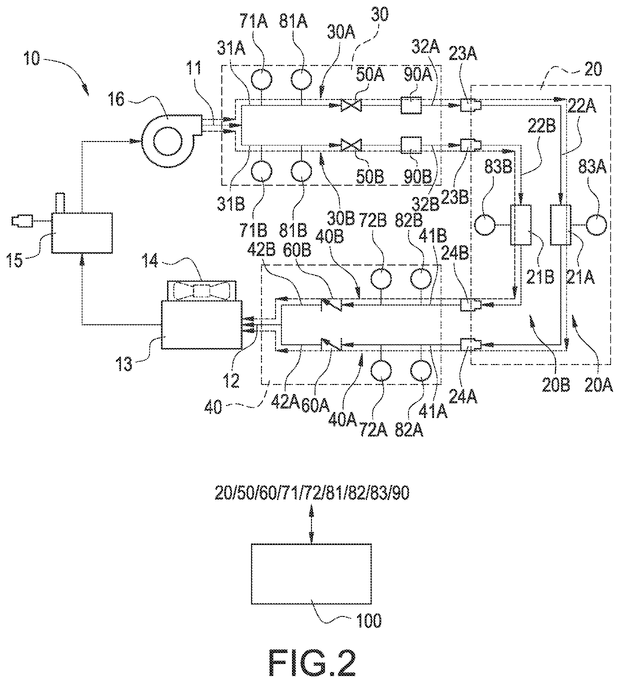
[0044]Please refer to FIG. 3, which shows a schematic diagram of the liquid-cooled charging equipment with multiple charging connector assemblies operating in a normal condition according to the present disclosure. In this embodiment, one of the two charging connectors (for example the first charging connector) is in a charging operation and the other charging connector (for example the second charging connector) is in an idle state. Since the first charging connector is normal in the charging operation, the first valve 50A corresponding to the first charging connector assembly 20A is opened. Therefore, the coolant from the recirculating cooling apparatus 10 flows to the first charging connector assembly 20A through the first coolant supply pipe 30A to cool the first charging connector assembly 20A. Also, the higher-temperature coolant that flows back to the recirculating cooling apparatus 10 through the first coolant return pipe 40A is cooled by the heat exchanger 13 cooperating wi...


PUM


Abstract

A liquid-cooled charging equipment with multiple charging connector assemblies includes a recirculating cooling apparatus, a plurality of charging connector assemblies, a plurality of coolant supply pipes, a plurality of coolant return pipes, a plurality of valves, and a control unit. The recirculating cooling apparatus has an outlet side and an inlet side. Each charging connector assembly includes a charging connector and a charging cable having an inlet end and an outlet end. Each valve is correspondingly disposed in each coolant supply pipe. The control unit is coupled to the valves and the charging connector assemblies. When the charging connector assemblies are in operation of charging, the control unit opens the valves corresponding to the charging connector assemblies to allow the low-temperature coolant provided by the recirculating cooling apparatus to flow through the coolant supply pipes to cool the charging connectors.

Description

BACKGROUNDTechnical Field[0001]The present disclosure relates to a charging equipment and a method of operating the same, and more particularly to a liquid-cooled charging equipment with multiple charging connector assemblies applied to electric vehicles and a method of operating the same.Description of Related Art[0002]The statements in this section merely provide background information related to the present disclosure and do not necessarily constitute prior art.[0003]With the development of the electric vehicle (EV) industry, modern EVs are usually loaded with large-capacity rechargeable batteries in order to increase the travel distance after being charged. In response to this technological development trend, fast EV charging equipment is generally designed to provide a relatively large output power (for example, 50 kW to 350 kW) to quickly charge EVs to avoid long waiting time of charging for car owners. However, the larger output power may cause the charging cable to generate ...

Claims


Application Information

Patent Timeline
IPC IPC(8): B60L53/302B60L53/16
CPCB60L53/302B60L53/16H01R13/6683H01R13/005
Inventor HSU, JUI-YUANHSIEH, MING-HSIENHUANG, KAI-HUNG
Owner DELTA ELECTRONICS INC
Why Eureka
Try Eureka