Dissepiment strainer plate inlet orifice clamping head

A membrane filter plate and feed port technology, which is applied in filtration and separation, separation methods, chemical instruments and methods, etc., can solve the expansion of the ring chuck, the inability to seal the combination of the membrane and the plate core, and affect the working efficiency of the membrane filter plate, etc. problem, to achieve the effect of novel structure design

Active Publication Date: 2010-07-14
杭州兴源环保设备有限公司
View PDF3 Cites 3 Cited by
  • Summary
  • Abstract
  • Description
  • Claims
  • Application Information

AI Technical Summary

Problems solved by technology

Its disadvantages: Since the ring chuck itself does not have expansibility, and the ring-shaped support chuck screwed into the ring-type chuck cannot expand the ring-type chuck, the force acting on the wall of the diaphragm feed port The force is only the radial force generated by the tight fit between the ring chuck and the diaphragm feed port, which is much smaller than the force generated by the diaphragm drum, which makes it impossible to seal the diaphragm and the plate core, resulting in Fluid seepage or leakage directly affects the working efficiency of the membrane filter plate

Method used


Image

  • Dissepiment strainer plate inlet orifice clamping head
  • Dissepiment strainer plate inlet orifice clamping head
  • Dissepiment strainer plate inlet orifice clamping head

Examples


Embodiment 1

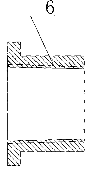
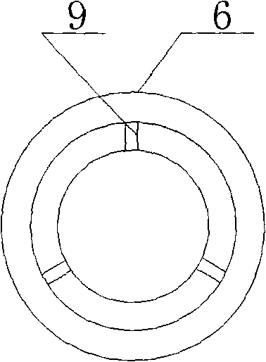
[0012] Embodiment 1: with reference to attached Figure 2-4 . Diaphragm filter plate feed inlet collet, it comprises hollow collet 6, flange collet 7, and hollow collet 6 wall has expansion wire groove 9 (this wire groove is through groove) and adopts mold injection molding. The flange chuck 7 is molded by injection molding and is screwed into the hollow chuck 6 to expand the wall of the hollow chuck 6. The inner wall of the hollow chuck 6 has a taper, and the outer wall of the flange chuck 7 has a taper. The taper matches the taper in the inner wall of the hollow collet 6, and the hollow collet 6 and the flange collet 7 are made of plastic or polymer material or metal material.

Embodiment 2

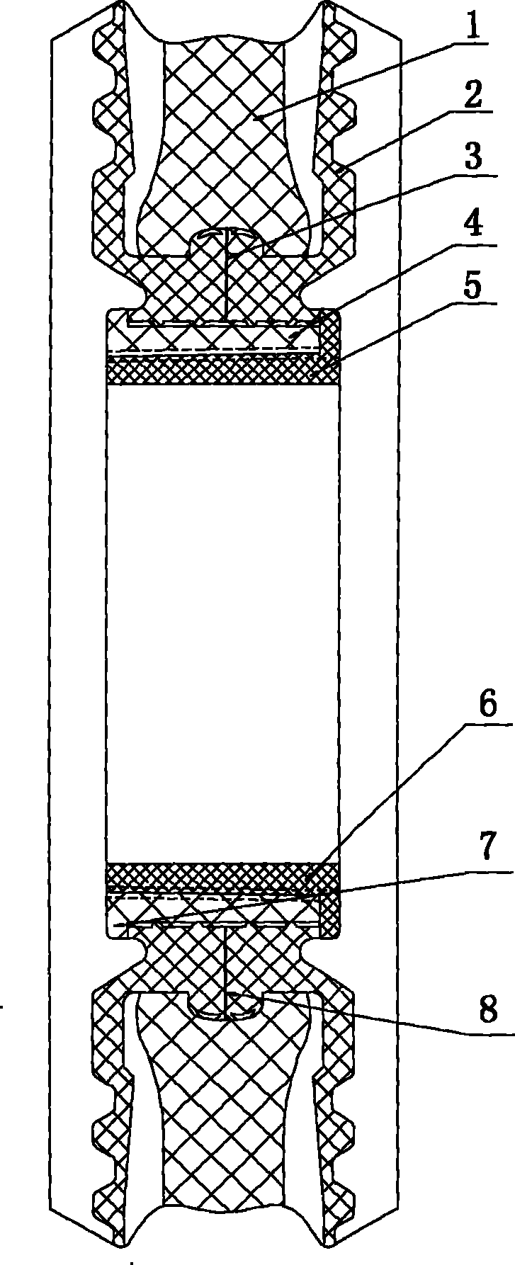
[0013] Embodiment 2: with reference to attached figure 1 . On the basis of Example 1, the diaphragm filter plate composed of the chuck of the inlet of the membrane filter plate has an annular groove on the wall of the inlet of the plate core and is injection molded or molded by injection molding or compression molding. The feeding port of the diaphragm 2 has a flanging structure and is made by the prior art, so it will not be described here. The back ring of the flange of the diaphragm feeding port is provided with a boss 4, the bottom of the boss 3 has one or two or more laps of lip 3, and the diaphragm portion adjacent to one or two or more laps of lip 3 has a concave The grooves form an open damping chamber 8 with one or two or more laps of the lip 3 respectively. The open damping chamber 8 and the groove in the plate core 1 are sealed and squeezed together, and the mouth surface of the feeding port of the diaphragm 2 is Concave-convex point distribution surface 5, expans...


PUM


Abstract

The invention relates to a membrane filter plate feed inlet clamp and a membrane filter plate feed inlet which is composed of the membrane filter plate feed inlet clamp, the wall of a plate core feed inlet is provided with an annular groove, the membrane feed inlet is a turning edge structure, the back part annular shape of the turning edge is provided with a boss, the bottom part of the boss is provided with one, two or more circles of lip edges, the membrane part which is adjacent to one, two or more circles of lip edges and one, two or more circles of lip edges constitute an open damping cavity respectively, the open damping cavity and the groove in the plate core are combined by sealed extrusion, the surface of the membrane feed inlet is a concave-convex point distributing surface, the wall of the hollow core clamp part is provided with an expansion line slot, the hollow core clamp is positioned in the membrane feed inlet, a flange clamp is screwed in the hollow core clamp and expands the wall of the hollow core clamp, and the membrane is radially sealed and tightened in the groove of the plate core by the hollow core clamp wall.

Description

technical field [0001] The invention relates to a diaphragm filter plate feed port chuck and a diaphragm filter plate feed port formed by the diaphragm filter plate feed port chuck, which belongs to the field of diaphragm filter plate manufacturing. Background technique [0002] Patent No. 200420065881.7, titled "Diaphragm Filter Plate Feed Port Chuck and Diaphragm Filter Plate Feed Port", the ring-shaped chuck of the diaphragm filter plate feed port chuck is located in the feed port of the diaphragm and is pulled The feeding port of the diaphragm is tightened on the filter plate core, and the ring-shaped support chuck is located in the ring-shaped chuck. Its disadvantages: Since the ring chuck itself does not have expansibility, and the ring-shaped support chuck screwed into the ring-type chuck cannot expand the ring-type chuck, the force acting on the wall of the diaphragm feed port The force is only the radial force generated by the tight fit between the ring chuck and t...

Claims


Application Information

Patent Timeline
Patent Type & Authority Patents(China)
IPC IPC(8): B01D25/176B01D25/30
Inventor 周立武
Owner 杭州兴源环保设备有限公司
Why Eureka
Try Eureka