Break-free machine injection and plastic type multipurpose shaft gland

A non-stop and shaft sealing technology, applied in the direction of engine sealing, mechanical equipment, engine components, etc., can solve the problems of poor sealing effect of seals, large economic losses, large leakage, etc., to achieve convenient disassembly and replacement and low manufacturing cost Low, simple structure effect

Inactive Publication Date: 2008-07-16
潘健
View PDF0 Cites 3 Cited by
  • Summary
  • Abstract
  • Description
  • Claims
  • Application Information

AI Technical Summary

Problems solved by technology

Due to mechanical wear and tear, after the equipment has been running for a period of time, the sealing effect of its seals will become worse and worse, and the leakage will increase accordingly. When the leakage reaches a certain level, the equipment will be forced to stop temporarily , to repair and replace the sealing parts. Due to the particularity of large-scale equipment such as steam turbines and generators, once it is shut down, it will often cause huge economic losses.
If the machine is not shut down, the equipment with a large amount of steam leakage will easily cause relatively large economic losses; while the equipment with a large amount of oil leakage will not only cause economic losses, but also have great potential safety hazards
[0003] At present, no technology has been found at home and abroad to complete the repair and replacement of the sealing part under the non-stop state of the equipment

Method used


Image

  • Break-free machine injection and plastic type multipurpose shaft gland
  • Break-free machine injection and plastic type multipurpose shaft gland
  • Break-free machine injection and plastic type multipurpose shaft gland

Examples


Embodiment 1

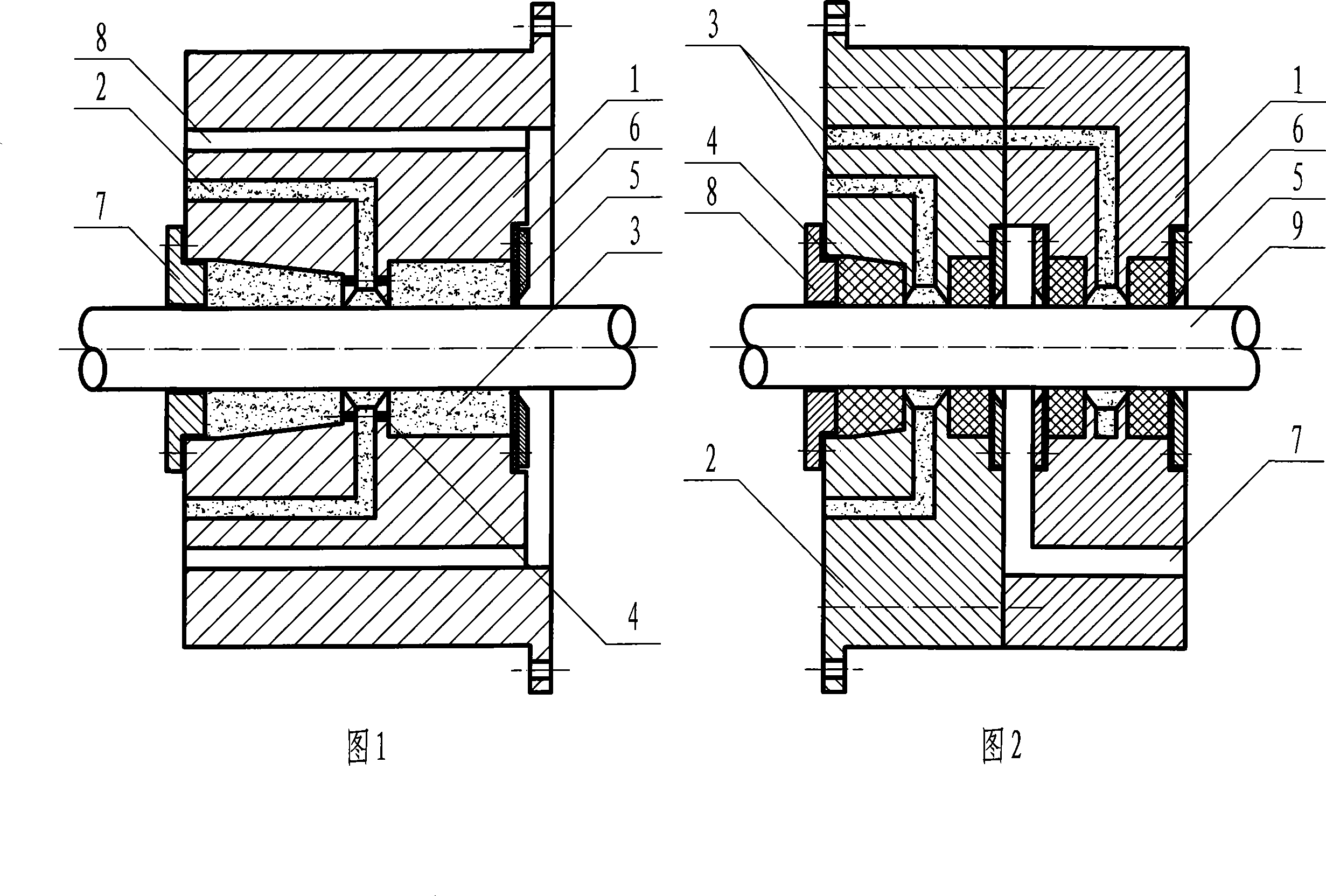
[0033] As shown in Figure 1, the non-stop injection and plastic multi-purpose shaft seal of the present invention has a structure including a single-stage sealing body 1, and an injection hole 2 is opened in the single-stage sealing body 1, and the end of the injection hole 2 is connected to a single-stage seal An annular sealed chamber surrounded by the body 1 and the rotating shaft. Filling chambers 3 are arranged on both sides of the annular sealed chamber. The injection hole 2 and the stuffing chamber 3 are connected through the distribution hole 4. A material blocking pad 5 and a material baffle plate 6 are arranged sequentially from the inside to the outside, and a gland 7 is arranged on the outside of the packing chamber 3 on the left side of the sealing body 1, and a pressure relief hole 8 penetrating left and right is opened on the single-stage sealing body 1 .

[0034] This sealing structure is used in conjunction with traditional seals such as labyrinth seals, that ...

Embodiment 2

[0036] As shown in Figure 2, the non-stop injection and plastic multi-purpose shaft seal of the present invention has a structure including a primary sealing body 1 and a secondary sealing body 2, and the primary sealing body 1 and the secondary sealing body 2 are respectively opened with The injection hole 3, the end of the injection hole 3 is connected to the annular sealing room surrounded by the first-level sealing body 1, the second-level sealing body 2 and the rotating shaft, the two sides of the annular sealing room are provided with a packing room, and the plastic sealing material 4 is arranged in the packing room. The outer side of the plastic sealing material 4 is provided with a material blocking pad 5 and a material blocking plate 6 sequentially from the inside to the outside, an oil return hole 7 is left between the above-mentioned two-stage sealing bodies, and a gland 8 is arranged on the outside of the secondary sealing body 2 . After the high-pressure oil leaks ...

Embodiment 3

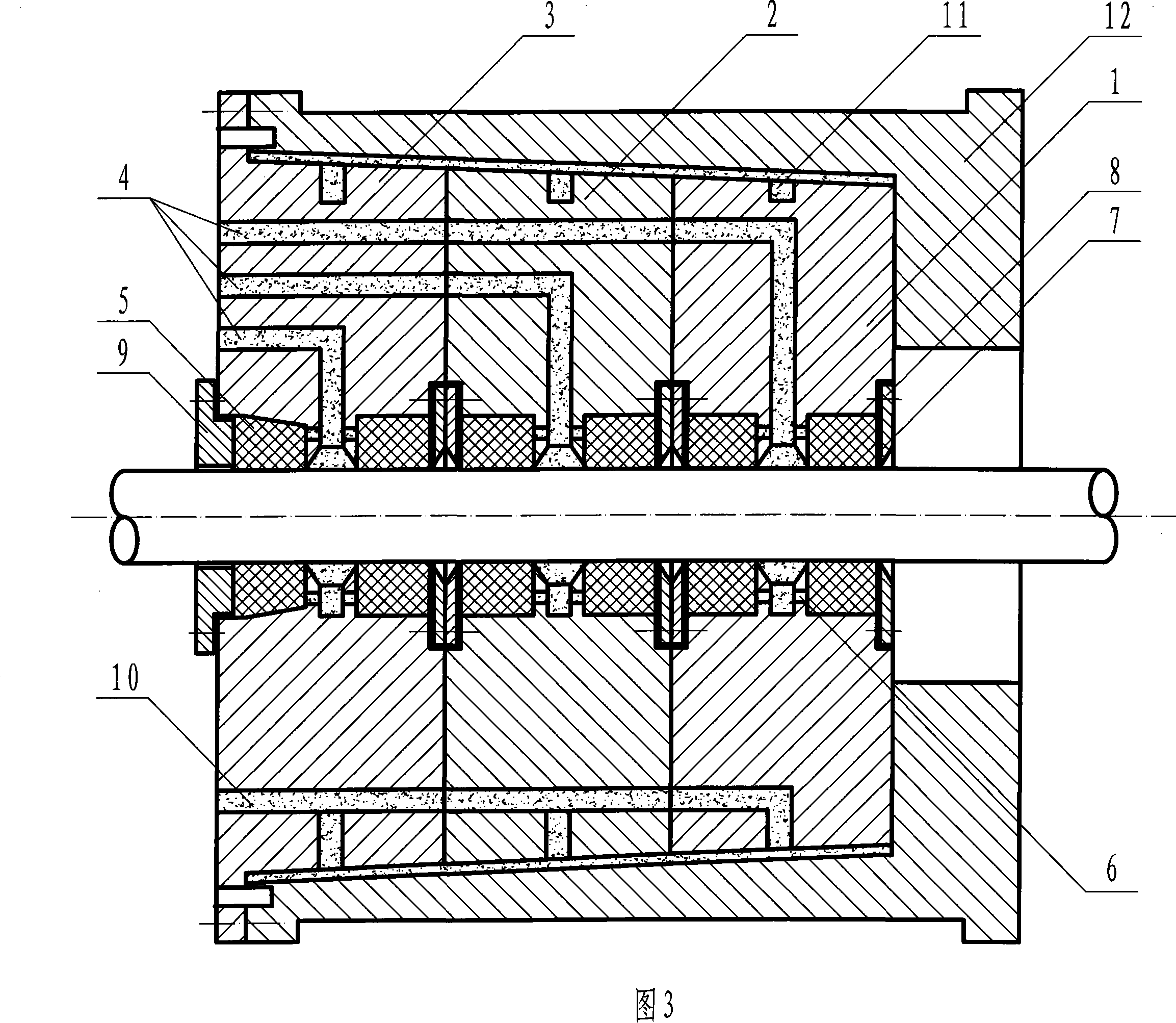
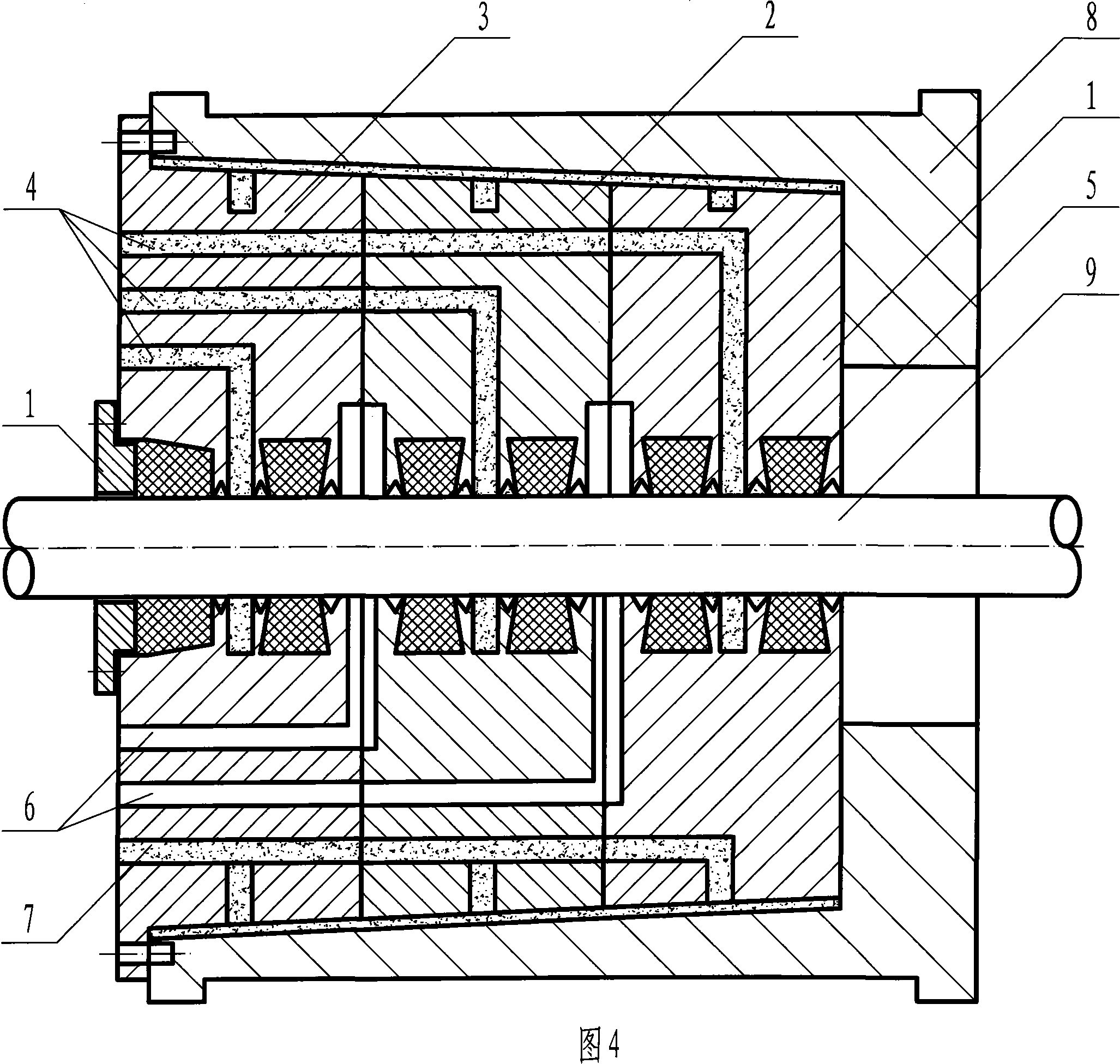
[0038] As shown in Figure 3, the non-stop injection and plastic multi-purpose shaft seal of the present invention has a structure comprising a first-level sealing body 1, a second-level sealing body 2 and a third-level sealing body 3 in a conical structure, and the first-level sealing body 1. There are injection holes 4 in the secondary sealing body 2 and the tertiary sealing body 3 respectively, and the ends of the injection holes 4 are connected to the ring formed by the primary sealing body 1, the secondary sealing body 2, the tertiary sealing body 3 and the rotating shaft Sealing chamber, the two sides of the annular sealing chamber are provided with packing chambers, and the plastic sealing material 5 is arranged in the packing chamber, the injection hole 4 and the packing chamber are connected through the material distribution hole 6, and the outside of the plastic sealing material 5 is arranged in sequence from the inside to the outside There is a material blocking pad 7...


PUM


Abstract

The invention provides an injection and molding typed multipurpose shaft seal without shutdown, belonging to the shaft end sealing technical field. The structure of the invention comprises a sealing body in first grade or higher than the first grade; the sealing body in each grade is internally provided with an injection molding hole; the end of the injection molding hole is communicated with the a cirque sealing chamber which is enclosed by the sealing body and a rotation shaft; the two sides of the cirque sealing chamber are provided with a packing chamber; corresponding sealing grease, sealing paste, sealing liquid or solid sealing material can be selectively injected into the injection molding hole according to different sealing parts, pressure and medium, thus preventing the internal and external leakage of the shaft seal. Compared with the prior art, the injection and molding typed multipurpose shaft seal without shutdown of the invention can be widely applied to the shaft end sealing of various rotation equipments in positive pressure and negative pressure, such as steam turbine, generator, water pump, fan, gearbox, etc., and can also be combined with the traditional seals, such as labyrinth seal, packing seal, mechanical seal, magnetic seal, etc. The invention can realize the overall sealing between the sealing body and the shaft, between the sealing body and a sealing sleeve, and between the sealing sleeve and the equipment. The invention can be suitable for the shaft seal of the equipment which is not concentric with the shaft. The sealing body and the sealing sleeve can be made into taper, thus realizing self sealing.

Description

(1) Technical field [0001] The invention relates to a shaft end sealing technology, in particular to a non-stop injection and plastic multi-purpose shaft seal which can complete the repair of leaking parts in a non-stop state. (2) Background technology [0002] Various positive and negative pressure rotating equipment in the prior art, such as steam turbines, generators, water pumps, fans, gearboxes, etc., most of the shaft end seals adopt sealing forms such as steam seals, water seals, and oil seals. Due to mechanical wear and tear, after the equipment has been running for a period of time, the sealing effect of its seals will become worse and worse, and the leakage will increase accordingly. When the leakage reaches a certain level, the equipment will be forced to stop temporarily , to repair and replace the sealing parts, due to the particularity of large-scale equipment such as steam turbines and generators, once it is shut down, it will often cause huge economic losses....

Claims


Application Information

Patent Timeline
Patent Type & Authority Applications(China)
IPC IPC(8): F16J15/20
Inventor 潘健
Owner 潘健
Why Eureka
Try Eureka