
Preparation method of self-sealing planar solid oxide fuel cell

A solid oxide and fuel cell technology, which is applied to fuel cell components, fuel cells, sealing/supporting devices, etc., to achieve the effect of solving sealing problems

Active Publication Date: 2017-04-19
浩燃科技(中山)有限公司
View PDF4 Cites 4 Cited by
  • Summary
  • Abstract
  • Description
  • Claims
  • Application Information

AI Technical Summary

Problems solved by technology

Using a similar method for sealing will bring about a series of problems, such as: the stability of the sealing material, the thermal expansion matching with other components of the battery stack, the thermal cycle life, the sealing effect, etc.

Method used

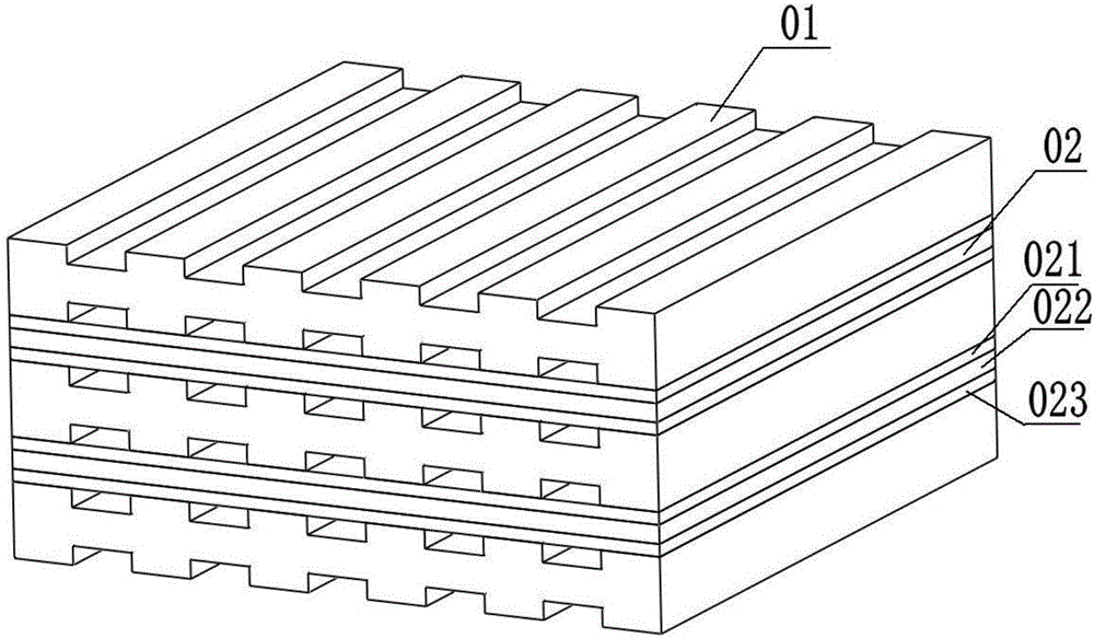

Image

  • Preparation method of self-sealing planar solid oxide fuel cell
  • Preparation method of self-sealing planar solid oxide fuel cell
  • Preparation method of self-sealing planar solid oxide fuel cell

Examples


preparation example Construction

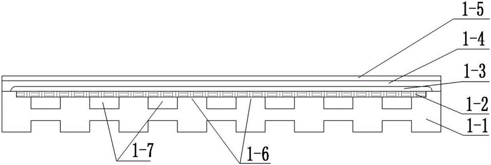
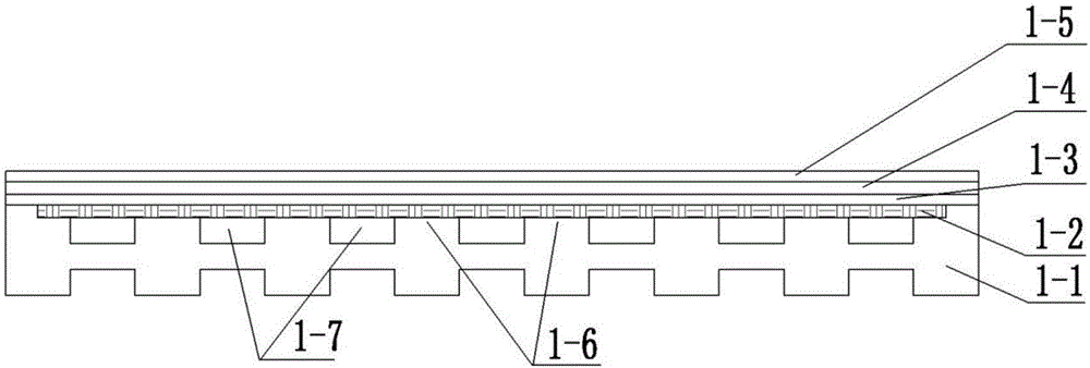
[0032] A method for preparing a self-sealing flat solid oxide fuel cell of the present invention comprises the following steps:

[0033] (1) Process the metal connection electrode 1-1 with a gas channel structure;

[0034] (2) forming a whole with the porous metal layer 1-2 and the technical connecting pole 1-1;

[0035] (3) Trimming the overall upper surface of the porous metal layer 1-2 and the metal connecting body 1-1 to form a surface available for spraying;

[0036] (4) Prepare a layer of anode layer 1-3 on the porous metal surface by thermal spraying;

[0037] (5) Prepare a layer of electrolyte layer 1-4 on the surface of the anode layer by thermal spraying;

[0038] (6) A cathode layer 1-5 is prepared on the surface of the electrolyte layer by thermal spraying.

Embodiment 1

[0040] in a 10×10cm 2 Process an outer bevel on the metal connecting pole 1-1 with a size of 9.1×9.1cm 2 , the inner groove size is 9×9cm 2 , a slope-like groove whose depth is equal to the thickness of the porous metal layer 1-2 (stainless steel), is placed in a 9×9cm 2 After the porous stainless steel, the porous metal layer 1-2 is connected to the metal connection electrode 1-1 by brazing, and the connection part includes the edge and the support surface 1 where the porous metal layer 1-2 contacts the metal connection electrode 1-1 -6. Then the surface of the porous metal layer 1-2 is ground, and the Ni / YSZ anode 1-3 (9.2×9.2cm 2 ), YSZ electrolyte layer 1-4 (10×10cm 2 ) and LSCF cathodes 1-5 (10×10cm 2 ), the single cell exhibited good voltage and power output.

Embodiment 2

[0042] in a 20×20cm 2 An outer bevel is processed on the metal connecting pole 1-1 with a size of 18.2×18.2cm 2 , the inner groove size is 18×18cm 2 , a slope-like groove with a depth equal to the thickness of the porous metal layer 1-2 (stainless steel), placed in a 18×18cm 2 After the porous stainless steel, the porous metal layer 1-2 is connected to the metal connecting electrode 1-1 by laser welding. Then the surface of the porous stainless steel is ground, and the Ni / ScSZ anode 1-3 (20×20cm 2 ), the ScSZ electrolyte layer 1-4 (20×20cm 2 ), the LSCF cathode 1-5 (20×20cm 2 ), thus completing the preparation of the battery.


PUM


Abstract

The invention discloses a preparation method of a self-sealing planar solid oxide fuel cell, wherein the preparation method comprises the following steps: (1) processing a metal connecting pole having a gas passageway structure; (2) allowing a porous metal layer and the metal connection pole to form a whole; (3) trimming the upper surface of the whole formed by the porous metal layer and the metal connection pole, to obtain a surface for spraying; (4) preparing an anode layer on the surface of the porous metal layer by a spraying method; (5) preparing an electrolyte layer on the surface of the anode layer by a spraying method; and (6) preparing a cathode layer on the surface of the electrolyte layer by a spraying method. Because the battery connecting pole and the porous stainless steel substrate are subjected to edge sealing treatment in advance, the self-sealing effect is realized after preparation of a battery is completed, and the problem of the sealing of the battery is effectively overcome.

Description

technical field [0001] The invention relates to the technical field of energy production, in particular to a preparation method of a self-sealing flat solid oxide fuel cell. Background technique [0002] A fuel cell is an electrochemical device that directly converts the chemical energy of reactants into electrical energy, and consists of an anode, an electrolyte, and a cathode. It can be divided into five categories: alkaline fuel cells, phosphate fuel cells, molten carbonate fuel cells, proton exchange membrane fuel cells and solid oxide fuel cells. Among them, the solid oxide fuel cell, which is a new generation of fuel cell, is considered to be a promising energy conversion device. First of all, its energy efficiency per unit volume and energy density per unit volume are high, which can realize high-power and high-efficiency power generation. If combined heat and power, its energy conversion efficiency can reach more than 80%; secondly, its gas pollutant emissions are a...

Claims


Application Information

Patent Timeline
Patent Type & Authority Applications(China)
IPC IPC(8): H01M8/02H01M8/0276
CPCH01M8/0271H01M8/0276H01M8/0286H01S5/183H01S5/022H01S5/024Y02E60/50
Inventor 李成新高九涛王岳鹏张山林杨冠军李长久
Owner 浩燃科技(中山)有限公司
Learn More