In-furnace heat adjusting system for horizontal high-temperature kiln

A high temperature, kiln technology, applied in the field of casting material processing equipment, can solve the problems of low energy utilization rate and high energy consumption, etc.

Active Publication Date: 2021-05-25
CHONGQING CHANGJIANG RIVER MOLDING MATERIAL GRP
View PDF17 Cites 0 Cited by
  • Summary
  • Abstract
  • Description
  • Claims
  • Application Information

AI Technical Summary

Problems solved by technology

[0004] But the roaster in the prior art consumes a lot of energy, and the energy utilization rate is low

Method used


Image

  • In-furnace heat adjusting system for horizontal high-temperature kiln
  • In-furnace heat adjusting system for horizontal high-temperature kiln
  • In-furnace heat adjusting system for horizontal high-temperature kiln

Examples


Embodiment 1

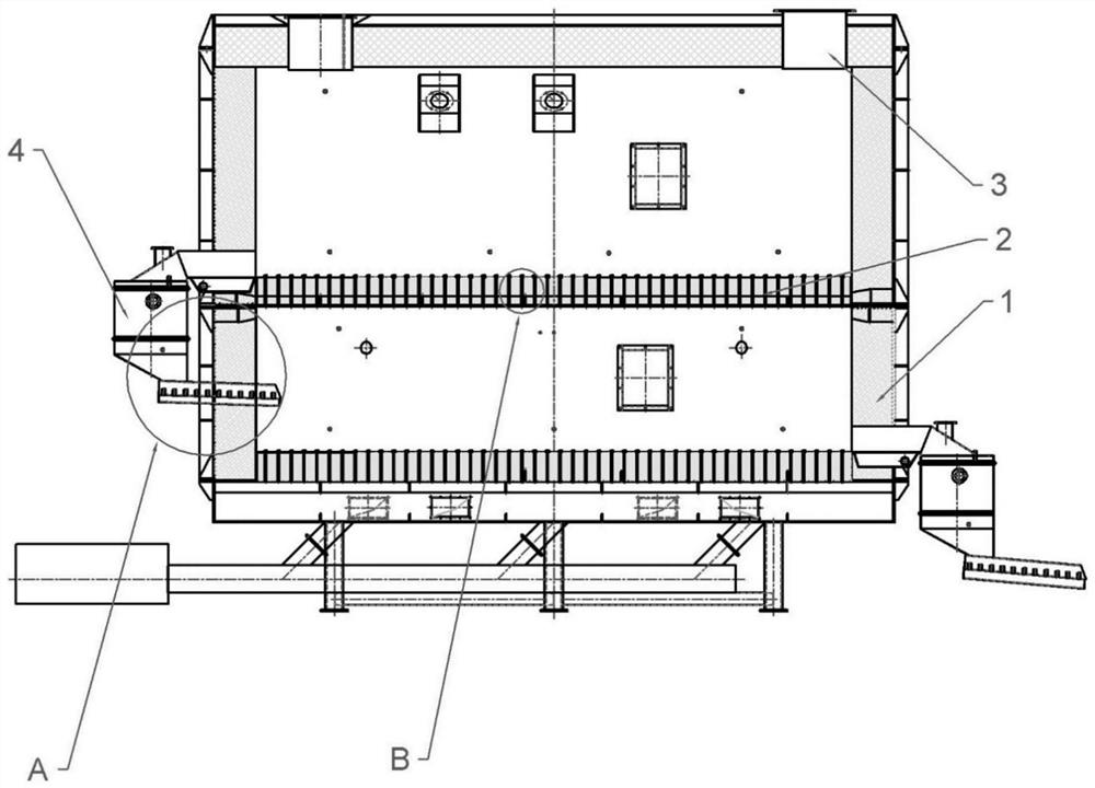
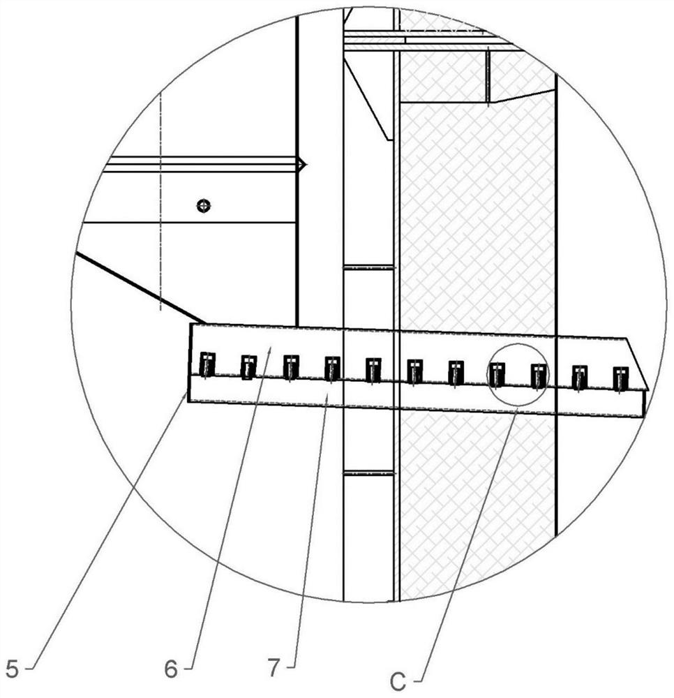
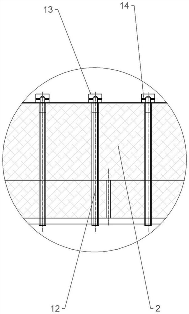
[0024] This embodiment is basically as attached figure 1 , figure 2 , image 3 with Figure 4 Shown: a furnace heat regulating system for a horizontal high-temperature kiln, including a furnace body 1, and a horizontal sealing plate 2 is arranged in the furnace body 1, and the sealing plate 2 divides the furnace body 1 into a first chamber and a second chamber chamber, the sealing plate 2 is evenly provided with a plurality of connecting pieces, the connecting piece includes a connecting pipe 12 and a wind cap 13, the connecting pipe 12 passes through the sealing plate and its lower end communicates with the second chamber, the upper end of the connecting pipe communicates with the wind cap 13, and the side of the wind cap Multiple air outlets 14 are provided. A connecting portion is provided on the side of the furnace body 1, and the connecting portion communicates with the first furnace body 1 and the second furnace body 1; the connecting portion includes a closed box 4 ...

Embodiment 2

[0029] Such as Figure 5 with Image 6 As shown, the difference between this embodiment and Embodiment 1 is that this embodiment also includes a sand separation structure. The sand distribution structure includes a first sand distribution part and a second sand distribution part (not shown in the figure), the second sand distribution part includes a connecting plate and a plurality of sand distribution rods, and a plurality of sand distribution rods are arranged side by side and their ends are connected to The connecting plates are connected, and gaps are provided between adjacent sand-distributing rods. The first sand dividing part includes two connecting rods 25 and a plurality of struts 26 , the two connecting rods 25 are hinged and each connecting rod 25 is connected with a plurality of struts 26 . In this embodiment, a first connecting rod 23 and a second connecting rod 24 are also included. The other ends of the first connecting rod 23 and the second connecting rod 24...


PUM


Abstract

The invention relates to the technical field of casting material treatment and discloses an in-furnace heat adjusting system for a horizontal high-temperature kiln. The system comprises a furnace body, wherein a transverse sealing plate is arranged in the furnace body, the sealing plate divides the furnace body into a first chamber and a second chamber, the sealing plate is uniformly provided with a plurality of communicating pieces, a side part of the furnace body is provided with a communicating part, and the communicating part communicates with a first furnace body and a second furnace body. The communicating part comprises a closing box and a sand discharging pipe, and the sand discharging pipe communicates with the lower part of the closing box; the sand discharging pipe is provided with a partition plate along a length direction, the partition plate divides the sand discharging pipe into a sand discharging cavity and an air cavity, the air cavity communicates with an air source, the sand discharging cavity is internally provided with a plurality of exhaust parts, the exhaust part comprises an outer pipe and an inner pipe, the upper end of the outer pipe is closed, the inner pipe is located in the outer pipe and two ends of the inner pipe communicate with the outer pipe and the air cavity respectively, and an air outlet is formed in the side part of the outer pipe; a discharge opening is formed in the side part of the furnace body, and a communicating part is arranged at the discharge opening and the length of the sand discharging pipe is greater than three times of the height of the sand discharging pipe. By adopting the system, an effect of saving energy sources can be achieved.

Description

technical field [0001] The invention relates to the technical field of mold material processing equipment, in particular to a furnace heat adjustment system for a horizontal high-temperature kiln. Background technique [0002] The roasting furnace is a kind of high-temperature kiln, and it is the main equipment of the thermal regeneration technology of foundry waste sand. By roasting the waste sand at high temperature, the coating layer on the surface of the waste sand will fall off, and the regeneration and reuse of the waste sand will be realized. [0003] At present, the commonly used furnace is a vertical two-layer roasting furnace. The upper part of the furnace body is connected with a feed pipe, and the inside of the furnace body is provided with a sealing plate. The bottom is connected with a discharge pipe and communicated with a main pipe, and a burner is arranged in the main pipe. The working process of the roaster is as follows: waste sand is added to the upper c...

Claims


Application Information

Patent Timeline
Patent Type & Authority Applications(China)
IPC IPC(8): F27B17/00F27D3/00F27D7/02F27D19/00
CPCF27B17/0016F27D3/0033F27D7/02F27D19/00F27D2019/0075
Inventor 熊帆熊鹰周高胜王德春陈方旭
Owner CHONGQING CHANGJIANG RIVER MOLDING MATERIAL GRP
Why Eureka
Try Eureka