Vehicle behavior control apparatus

A technology for controlling equipment and vehicles, which is applied to vehicle parts, control valves, air release valves, brakes, etc., and can solve problems such as bad and uncomfortable

Inactive Publication Date: 2008-12-03
HITACHI LTD
View PDF3 Cites 5 Cited by
  • Summary
  • Abstract
  • Description
  • Claims
  • Application Information

AI Technical Summary

Problems solved by technology

This results in the controlled internal pressure of the wheel cylinders being transmitted to the brake pedal
This can transmit a bad or uncomfortable feeling to the driver through the brake pedal, especially when the controlled internal pressure of the wheel cylinder is high and the vibration frequency of the pressure is high

Method used


Image

  • Vehicle behavior control apparatus
  • Vehicle behavior control apparatus
  • Vehicle behavior control apparatus

Examples


Embodiment 1

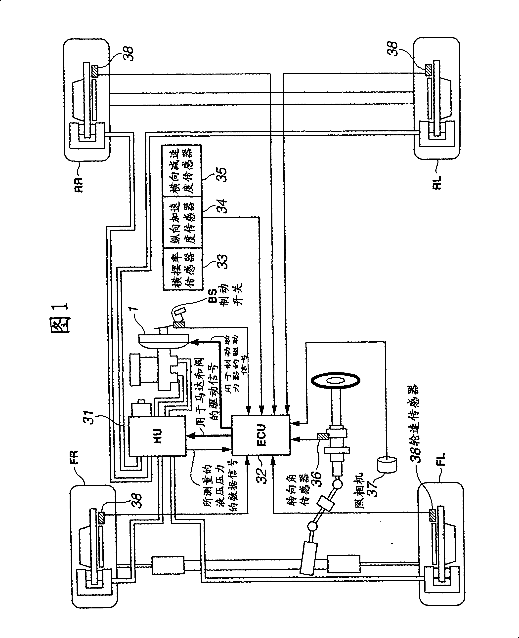
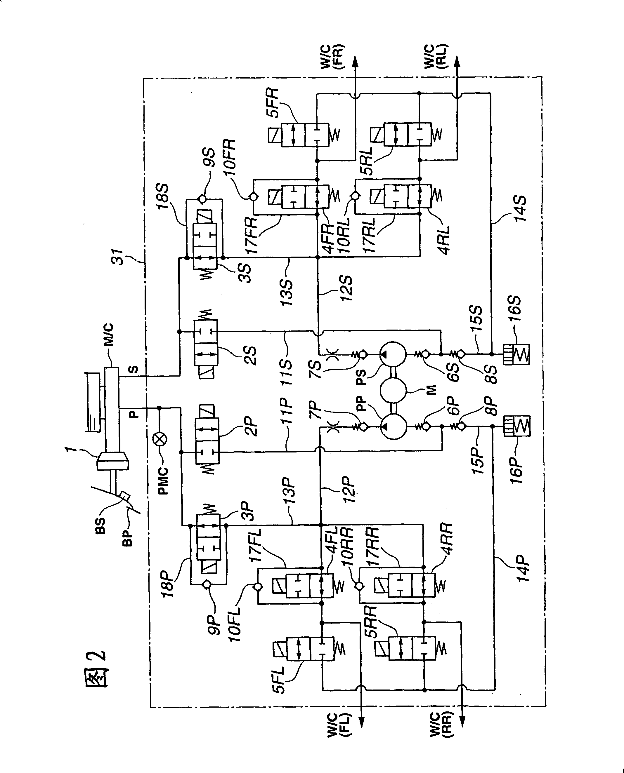
[0038] FIG. 1 schematically shows a system configuration of an automobile provided with a vehicle behavior control device or system according to a first embodiment of the present invention. The car includes front left wheels "FL" (first wheels), front right wheels "FR" (second wheels), rear left wheels "RL" (third wheels), rear right wheels "RR" (fourth wheels). The vehicle behavior control apparatus includes: an electronically controlled brake booster 1 for controlling the master cylinder pressure independently of the brake pedal operation; a brake unit 31 for controlling the wheel cylinder pressures of the wheels FL, FR, RL, and RR; and the electric control unit 32 for controlling the electronically controlled brake booster 1 and the electric control unit 32 by sending command signals or control signals to them.

[0039] The control unit 32 is configured to receive data signals from a brake switch "BS", a yaw rate sensor 33, a longitudinal acceleration sensor 34, a lateral ...


PUM


Abstract

A hydraulic circuit includes a first pressurizing section for pressurizing a wheel cylinder by operating a master cylinder, and a second pressurizing section for pressurizing the wheel cylinder independently of operation of the master cylinder. A control unit determines whether a first operation request according to a physical relationship between a vehicle and an environment surrounding the vehicle is present; determines whether a second operation request according to a physical behavior of the vehicle is present; activates the first pressurizing section when the first operation request is present and the second operation request is absent; activates the second pressurizing section when the first operation request is absent and the second operation request is present; ; and keeps the first pressurizing section activated and activates the second pressurizing section, when the second operation request turns present under condition that the first pressurizing section is activated in response to the first operation request.

Description

technical field [0001] The present invention relates to a vehicle behavior control device or system for assisting a driver in properly operating a vehicle and / or preventing the vehicle from entering undesired operating states. Background technique [0002] Japanese Patent Application Publication No. 2000-255405 discloses a brake control device for a vehicle. The brake control device includes a brake booster which is controlled to adjust the internal pressure of the master cylinder independently of the driver's operation of the brake pedal. When the vehicle is in the state of oversteer or understeer, the brake control device controls the behavior of the vehicle by driving the brake booster and adjusting the internal pressure of the wheel cylinder. [0003] According to Japanese Patent Application Laid-Open No. 2000-255405, during operation of the brake control device, fluid communication is allowed between the wheel cylinder and the master cylinder, which are objects of cont...

Claims


Application Information

Patent Timeline
Patent Type & Authority Applications(China)
IPC IPC(8): B60T8/24B60T8/34B60T8/58B60T7/12B60T8/1755
CPCB60T8/4872B60T8/1755B60T2201/03B60T8/4081
Inventor 斋藤隆允樋熊元宏
Owner HITACHI LTD
Why Eureka
Try Eureka