Backward warming system of boiler feed pump

A technology of boiler feed water pump and feed water pump, which is applied in the direction of controlling feed water, pump components, variable capacity pump components, etc., can solve problems such as high water pressure and easy bursting of pipelines, and achieve lower water pressure, save pipeline consumption, and improve maintenance efficiency effect

Active Publication Date: 2014-04-30
POWERCHINA HEBEI ELECTRIC POWER SURVEY & DESIGN INST CO LTD
View PDF5 Cites 5 Cited by
  • Summary
  • Abstract
  • Description
  • Claims
  • Application Information

AI Technical Summary

Problems solved by technology

[0006] The technical problem to be solved in the present invention is to provide a boiler feed water pump heating system to solve the problem of high water pressure and easy bursting of pipes in the traditional heating system

Method used


Image

  • Backward warming system of boiler feed pump
  • Backward warming system of boiler feed pump
  • Backward warming system of boiler feed pump

Examples


Embodiment 1

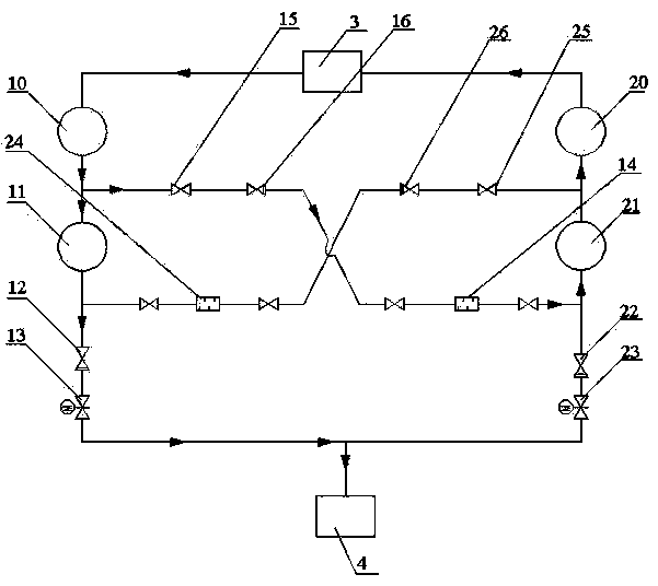
[0030] A boiler feed water pump heating system, such as figure 2 As shown, it includes a first pipeline and a second pipeline, and the first pipeline and the second pipeline are arranged in parallel between the deaerator 3 and the high pressure heater 4 . On the first pipeline, a first prepump 10 , a first feed water pump 11 , a first check valve 12 and a first electric valve 13 are sequentially connected in series from one end of the deaerator 3 . On the second pipeline, a second pre-pump 20 , a second feed water pump 21 , a second check valve 22 and a second electric valve 23 are connected in series from one end of the deaerator 3 . The inlets of the first prepump 10 and the second prepump 20 communicate with the deaerator 3 respectively, and the outlets of the first electric valve 13 and the second electric valve 23 communicate with the high pressure heater 4 . Wherein the first feedwater pump 11 and the second feedwater pump 21 are high-pressure pumps, and the first pre-...

Embodiment 2

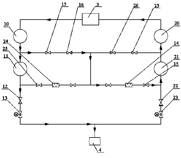
[0037] Such as image 3 As shown, the difference from Embodiment 1 is that the pipeline between the first bypass check valve 16 and the first cut-off valve 15 located in the middle of the first bypass, and the second bypass check valve 26 and the second bypass check valve The pipelines between the second shut-off valves 25 in the middle of the bypass are merged into one common pipeline.

[0038] On the one hand, this setting can save space in the turbine room and make the layout of the turbine room more reasonable; on the other hand, it can save the amount of pipelines and reduce costs.

Embodiment 3

[0040] Such as Figure 4 As shown, the difference with Embodiment 1 is:

[0041] A first bypass check valve 16, a common throttling orifice 54 and three first cut-off valves 15 are arranged on the first bypass. The non-return valve 16, the common throttling orifice 54, the first cut-off valve 15, and the first cut-off valve 15 are sequentially arranged in series.

[0042] The second bypass includes three sections of pipelines: pipeline I, pipeline II and pipeline III. The pipeline I is connected between the outlet of the second prepump 20 and the outlet of the first bypass check valve 16, and a second cut-off valve 25 and a The second bypass check valve 26 .

[0043] Pipeline II is a pipeline connected between the outlet of the first bypass check valve 16 and the inlet of the first stop valve 15 in the middle of the first bypass, that is, this section of pipeline is the first bypass and the second bypass. public pipelines. The common orifice plate 54 on the pipeline II is...


PUM


Abstract

The invention discloses a backward warming system of a boiler feed pump. The backward warming system of the boiler feed pump comprises a first pipeline and a second pipeline which are arranged between a deaerator and a high-pressure heater, a first booster pump, a first feed pump, a first check valve and a first motorized valve are serially arranged on the first pipeline, a second booster pump, a second feed pump, a second check valve and a second motorized valve are serially arranged on the second pipeline, both the first booster pump and the second booster pump are medium-pressure pumps, a first bypass is arranged between an outlet of the first booster pump and an outlet of the second feed pump, a second bypass is arranged between an outlet of the second booster pump and an outlet of the first feed pump, and a plurality of check valves, throttling orifice plates and check valves are serially arranged on each of the first bypass and the second bypass. The backward warming system of the boiler feed pump has the advantages of simple structure and reasonable arrangement, eroding of pump warming water to pipelines can be reduced obviously, and water pressure that pump warming water pipelines loaded can be lowered obviously, so that possibility of pipeline burst is lowered, safety of water pipes is improved, and maintenance cost caused by water pipe crack is reduced.

Description

technical field [0001] The invention relates to a boiler maintenance device of a thermal power plant, in particular to a heating pump system of a boiler feed water pump. Background technique [0002] The temperature of the conveying medium of the boiler feed water pump is generally higher than 130°C, so the pump must be warmed up. The reason is that after the feed water pump stops running, the residual water inside the feed water pump will gradually cool down and sink to the bottom of the feed water pump, while the hotter water will Raise to the upper part of the pump, so that there is a temperature difference between the upper part and the lower part of the pump body of the feed water pump, which will cause different degrees of thermal expansion between the upper part and the lower part of the pump body, resulting in changes in the internal running clearance of the boiler feed water pump, which is not conducive to the safe start of the feed water pump . If the feed water p...

Claims


Application Information

Patent Timeline
Patent Type & Authority Applications(China)
IPC IPC(8): F22D1/50F22D5/34F04B53/08
Inventor 赵雅旋孙辰军董舟李青松焦莉李双江徐培培
Owner POWERCHINA HEBEI ELECTRIC POWER SURVEY & DESIGN INST CO LTD
Why Eureka
Try Eureka