
Anti-air-erosion dewatering regulating valve

A technology of anti-cavitation and regulating valve, which is applied in the directions of steam traps, sliding valves, valve details, etc., can solve the problems of cavitation, non-applicable zero leakage, sealing ring damage, etc. Corrosion, prolong service life, reduce the effect of erosion and damage

Active Publication Date: 2013-08-14
HARBIN SONGLIN POWER STATION EQUIP CO LTD
View PDF8 Cites 17 Cited by
  • Summary
  • Abstract
  • Description
  • Claims
  • Application Information

AI Technical Summary

Problems solved by technology

Under the design working conditions, the valve pressure difference of #1-#3 high pressure and crisis drain regulating valve is 8.353MPa, 5.018MPa and 2.289MPa respectively, and the medium temperature is 298℃, 264℃ and 183.5℃ respectively, that is to say the above Cavitation generally occurs in the #1 and #2 high-intensity crisis drain valves used under working conditions
(2) The valve adopts a balanced spool form: a sealing ring is designed on the disc, or called a balanced seal, which is used to cut off the medium, and the closing level (leakage level) of the sealing seat is mostly ANSI Ⅳ level; The loaded sealing ring can reach ANSI V level, but in long-term use, due to wear and other reasons, the sealing ring will often be damaged, resulting in greater leakage
Although the balanced spool form can form a smaller valve driving force and use a smaller actuator, it is often not suitable for working conditions that require zero leakage

Method used


Image

  • Anti-air-erosion dewatering regulating valve
  • Anti-air-erosion dewatering regulating valve
  • Anti-air-erosion dewatering regulating valve

Examples


Embodiment Construction

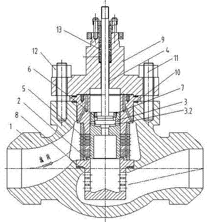
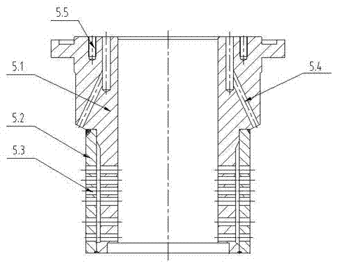
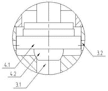
[0028] see Figure 1-4 , the present invention provides an anti-cavitation and water-repelling regulating valve, comprising a valve body 1, a valve seat 2 fixed in the valve cavity surrounded by the valve body, and its sealing surface and the sealing surface of the valve seat constitute the main seal The auxiliary valve disc 3 and the valve stem 4 that drives the valve disc to rise and fall in a straight line, a throttling sleeve 5 is fixed in the valve cavity on the medium inlet side, and a section of the outer diameter of the throttle sleeve is matched with a section of the inner wall of the valve cavity. Maintaining coaxiality, the lower end of the throttling sleeve abuts against the non-sealing surface of the upper end of the valve seat. The throttling sleeve and the valve seat divide the medium inlet side valve cavity into two parts, the inner part and the outer part of the throttling sleeve. The throttling sleeve is welded by the inner sleeve 5.1 and the outer sleeve 5....


PUM


Abstract

The invention relates to an anti-air-erosion dewatering regulating valve comprising a valve body, a valve seat, valve clacks and a valve rod. The valve seat is fixed in a valve cavity encircled by the valve body, the sealing surfaces of the valve clacks and the sealing surface of the valve seat form a main sealing pair, the valve rod drives the valve clacks straightly up and down, a orifice sleeve is fixedly arranged in a valve cavity at a medium inlet, the lower end of the orifice sleeve is abutted against the non-sealing surface of the upper end of the valve seat, the valve cavity at the medium inlet is divided into an inner portion and an outer portion by the orifice sleeve and the valve seat, multilayer sleeves are sleeved layer by layer to form the orifice sleeve, a gap is reserved between each layer of the lower portion of the orifice sleeve, a plurality of orifices are radially reserved on the sleeve wall of each sleeve layer, and external diameter surfaces of the valve clacks are slidingly matched with the inner diameter surfaces of the orifice sleeve. The anti-air-erosion dewatering regulating valve has the advantages of no erosion, small required executive force, reliable sealability, wear resistance, washout proof, simple structure, convenient mounting, long service life and the like. Erosion can be avoided under the working condition of big differential and the anti-air-erosion dewatering regulating valve can be driven by a small actuator.

Description

technical field [0001] The invention relates to a drain regulating valve, in particular to a cavitation-resistant drain regulating valve suitable for use under high-temperature and high-pressure working conditions, and is mainly applicable to the steam turbine side and boiler side of supercritical units and ultra-supercritical units of large-scale power stations in the hydrophobic system. Background technique [0002] Regulatory valves, as executive parts in automatic control and regulation systems, are widely used in modern industrial production, and their control and communication methods have undergone fundamental changes with the application of new computer and bus technologies, greatly improving the accuracy of control and reliability. However, in the process of using under high temperature and high pressure conditions, the pipeline fluid often causes cavitation due to improper design of equipment structure, installation or process parameters, which causes serious dama...

Claims


Application Information

Patent Timeline
Patent Type & Authority Applications(China)
IPC IPC(8): F16K47/08F16K3/24F16K3/314F16K39/04F16T1/00
Inventor 于艳敏许文波边久海
Owner HARBIN SONGLIN POWER STATION EQUIP CO LTD
Learn More