Jet-propelled flap lift augmentation joined wing system and aircraft thereof

A technology of jet flaps and connecting wings, applied in the field of aircraft, can solve the problems of reducing lift coefficient, high noise, and high jet velocity of the engine, and achieve the effects of reducing structural weight, low noise, and low dead weight

Active Publication Date: 2015-11-11
江苏中孚动力产业链有限公司
View PDF7 Cites 17 Cited by
  • Summary
  • Abstract
  • Description
  • Claims
  • Application Information

AI Technical Summary

Problems solved by technology

[0003] The jet-type upper-wing-blown flap lift system can accelerate the jet flow of the jet engine to accelerate the flow of the airflow on the upper wing surface. The flow is also powered up on the upper surface of the wing, the jet velocity is high, and the noise and vibration caused by the scouring of the upper wing skin are large; the jet temperature is high, so the upper wing skin and the The ablation of the wing structure is serious, and the requirements for the skin and wing structure are high. Another disadvantage is that the engine jet velocity is high and the noise is loud during takeoff and landing.
[0004] The jet-type lower wing blowing flaps increase lift system can make the jet flow of the jet engine pass through the trailing edge slats of the wings to accelerate the airflow on the upper wing surface of the wing. , and the high-speed jet flow of the jet engine flows through the lower surface of the wing at a short distance during the cruising stage, which reduces the air pressure on the lower surface, reduces the lift coefficient, and makes the cruise efficiency of the wing low; another disadvantage is that the engine High jet speed, loud noise

Method used


Image

  • Jet-propelled flap lift augmentation joined wing system and aircraft thereof
  • Jet-propelled flap lift augmentation joined wing system and aircraft thereof
  • Jet-propelled flap lift augmentation joined wing system and aircraft thereof

Examples


Embodiment Construction

[0020] The present invention will be further described in detail below in conjunction with the accompanying drawings and embodiments.

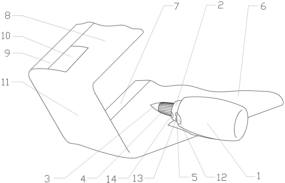
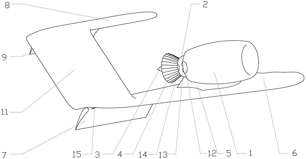
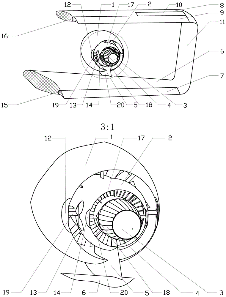
[0021] Such as figure 1 , 2 , 3, 4, 5, 6, 7, and 8, the jet-flap increase-lift connecting wing system of the present invention comprises a turbofan engine, a wing, a pylon 5 connecting the turbofan engine and the wing, and the turbofan engine has The turbine shaft rectifying cone 3, the wing has trailing edge flaps, the turbine shaft rectifying cone 3 is extended backward for a certain length, and the multi-fish scale type convergent and diffusing nozzle 4 is arranged on it, and there is one on the left and right sides of the outer duct nozzle. For the airflow convergence and diffusion device for the jet flow in the external channel, there is also an airflow convergence and diffusion device for the jet flow in the inner channel on the left and right sides of the nozzle of the inner channel. The airflow converging and diffusing device for the...


PUM


Abstract

The invention discloses a jet-propelled flap lift augmentation joined wing system. The jet-propelled flap lift augmentation joined wing system comprises a turbofan engine, an airfoil, a hanger and a turbine shaft rectifying cone, wherein the airfoil is provided with a rear-edge flap, the turbine shaft rectifying cone extends backwards for a given length and is provided with a plurality of scale-type convergence dispersion spray pipes, the left side and the right side of an outer duct spray opening are respectively provided with an airflow convergence dispersion apparatus consisting of an outer front edge and two outer convergence dispersion sheets, the left side and the right side of an inner duct spray opening are respectively provided with an airflow convergence dispersion apparatus consisting of an inner front edge and two inner convergence dispersion sheets, the airfoil is a joined wing. When the jet-propelled flap lift augmentation joined wing system takes off and lands perpendicularly, an upward lift resultant force can be generated; when the jet-propelled flap lift augmentation joined wing system flies in a level cruising manner, a thrust force and a lift force can be generated; an aircraft utilizing the jet-propelled flap lift augmentation joined wing system disclosed by the invention can vertically take off and land and fly at a high speed and can be stably switched between the vertical taking-off and landing and high-speed flight.

Description

technical field [0001] The invention relates to a jet-type external blowing flap increasing-lift system, in particular to a jet-type flap increasing-lift connecting wing system and an aircraft using the jet-type flap increasing-lift connecting-wing system. Background technique [0002] There are two kinds of known jet-type external blowing flap lift-increasing systems, the one is the jet-type upper wing surface blown flap lift-increasing system, and the other is the jet-type lower wing surface blown flap increase-lift system. [0003] The jet-type upper-wing-blown flap lift system can accelerate the jet flow of the jet engine to accelerate the flow of the airflow on the upper wing surface. The flow is also powered up on the upper surface of the wing, the jet velocity is high, and the noise and vibration caused by the scouring of the upper wing skin are large; the jet temperature is high, so the upper wing skin and the The ablation of the wing structure is serious, and the r...

Claims


Application Information

Patent Timeline
Patent Type & Authority Applications(China)
IPC IPC(8): B64C13/00B64C9/38B64C9/28
Inventor 龙川
Owner 江苏中孚动力产业链有限公司
Why Eureka
Try Eureka