Electromagnetic actuator and electromagnetic execution system
An electromagnetic actuator and valve body technology, applied in the field of electromagnetic valves, can solve problems such as large leakage, large gaps, and cavitation of parts, and achieve the effects of reducing the probability of leakage, strengthening the force, and good sealing
- Summary
- Abstract
- Description
- Claims
- Application Information
AI Technical Summary
Problems solved by technology
Method used
Image
Examples
Embodiment 1
[0048] This embodiment provides an electromagnetic actuator, which can be used in a high-pressure environment, has good sealing performance, and reduces the probability of leakage.
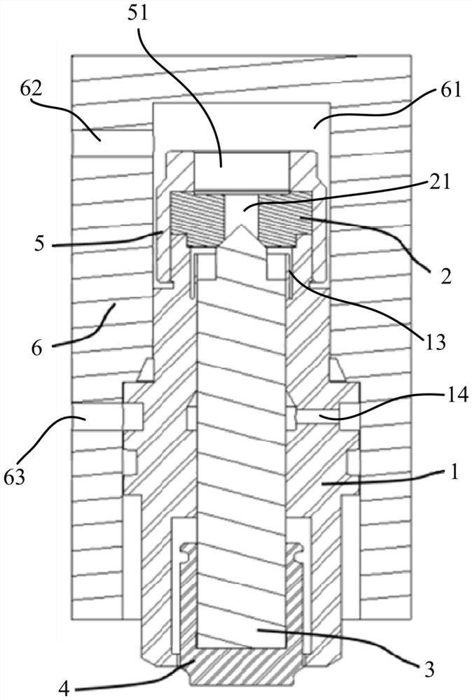
[0049] Such as figure 1 As shown, the electromagnetic actuator includes a valve body 1 , a valve seat 2 and a valve core 3 .
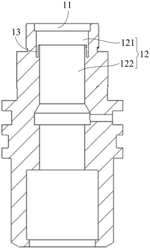
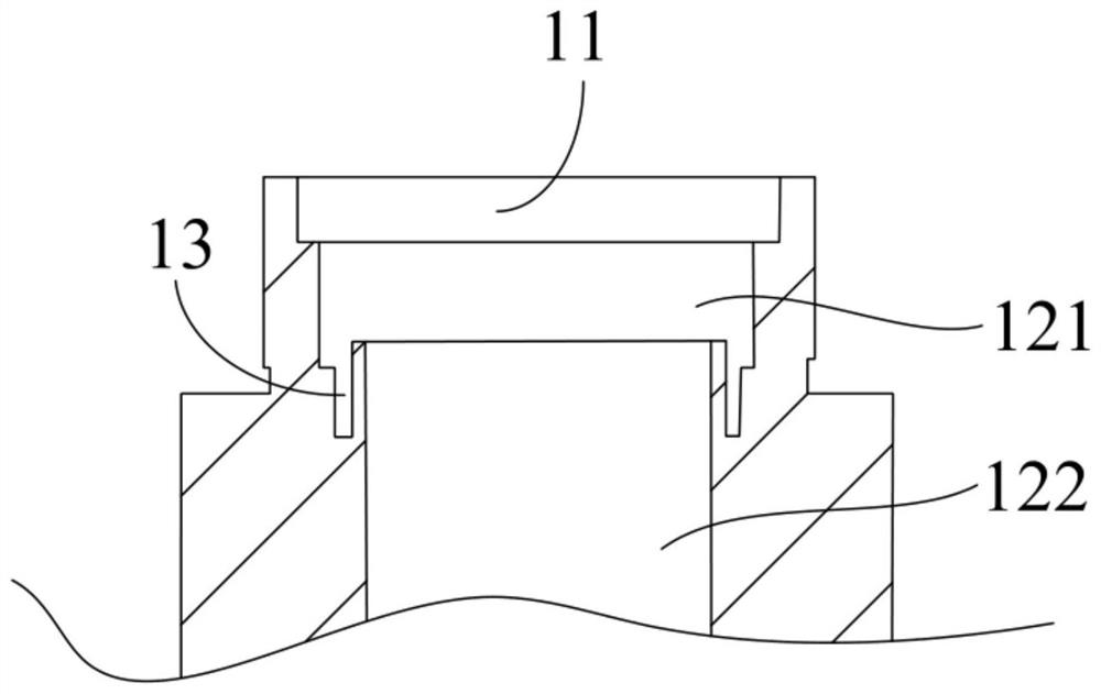
[0050] Among them, such as figure 2 As shown, the valve body 1 has a connecting mounting hole 11 and a central hole 12 . The aperture of mounting hole 11 is greater than the aperture of middle hole 12, and mounting hole 11 is used for installing valve seat 2, that is, valve seat 2 is installed in mounting hole 11, in some embodiments, as figure 1 As shown, the cross section of the valve seat 2 is T-shaped, the bottom end of the valve seat 2 extends into the installation hole 11 , and the top end of the valve seat 2 is located outside the valve body 1 and cooperates with the top end of the valve body 1 . The valve seat 2 has a first through hole 21 communicating with th...
Embodiment 2
[0070] The difference between the electromagnetic actuator provided in this embodiment and the first embodiment is that the groove 13 in this embodiment is provided on the valve core 3 .
[0071] Specifically, such as Image 6 As shown, the valve core 3 is provided with a groove 13 communicating with the first through hole 21. The depth direction of the groove 13 is parallel to the extending direction of the valve body 1. The groove 13 is used to accommodate the high-pressure fluid so that the high-pressure fluid can squeeze out Press the spool 3 against the valve body 1.
[0072] Further, the spool 3 includes a large cylindrical section 31, a small cylindrical section 32 and a conical section 33 connected in sequence. The end surface of the large cylindrical section 31 connected to the small cylindrical section 32 is provided with a groove 13, and the high-pressure medium flows into it. When the groove 13 is formed, the groove wall of the groove 13 can be squeezed close to t...
Embodiment 3
[0075] The difference between the electromagnetic actuator provided in this embodiment and the embodiment is that grooves 13 are provided on both the valve body 1 and the valve core 3 in this embodiment.
[0076] Specifically, such as Figure 7 As shown, the spool 3 includes a large cylindrical section 31, a small cylindrical section 32 and a conical section 33 connected in sequence. The end surface of the large cylindrical section 31 connected to the small cylindrical section 32 is provided with a groove 13, and the middle hole 12 includes a large hole section 121 and a small hole section 122. The aperture of the large hole section 121 is larger than the aperture of the small hole section 122. The intersection of the large hole section 121 and the small hole section 122 forms a junction surface, and the junction surface is provided with the above-mentioned groove 13 . By arranging two grooves 13, the groove walls of the two grooves 13 are close to each other and closely atta...
PUM
 Abstract
Description
Claims
Application Information
 - R&D
- Intellectual Property
- Life Sciences
- Materials
- Tech Scout
- Unparalleled Data Quality
- Higher Quality Content
- 60% Fewer Hallucinations
Browse by: Latest US Patents, China's latest patents, Technical Efficacy Thesaurus, Application Domain, Technology Topic, Popular Technical Reports.
© 2025 PatSnap. All rights reserved.Legal|Privacy policy|Modern Slavery Act Transparency Statement|Sitemap|About US| Contact US: help@patsnap.com


