Double collet connector assembly for bone anchoring element

a technology of connectors and bones, applied in the field of connecting rod connectors, can solve the problems of pedicle screws, rods must be bent after, etc., and achieve the effect of enhancing the wedging for

Inactive Publication Date: 2010-09-07
EXPANDING ORTHOPEDICS
View PDF6 Cites 102 Cited by
  • Summary
  • Abstract
  • Description
  • Claims
  • Application Information

AI Technical Summary

Benefits of technology

[0003]The present invention seeks to provide an improved connector assembly for connecting rods and the like to bone anchoring elements, such as pedicle screws, as is described more in detail hereinbelow. The connector assembly of the invention permits rotational and translational adjustments before locking the rod in place. The connector assembly of the invention includes a double collet assembly with enhanced wedging force.

Problems solved by technology

Some systems have a disadvantage in that the rod must be bent after coupling to the pedicle screw because of anatomical considerations.

Method used


Image

  • Double collet connector assembly for bone anchoring element
  • Double collet connector assembly for bone anchoring element
  • Double collet connector assembly for bone anchoring element

Examples


Embodiment Construction

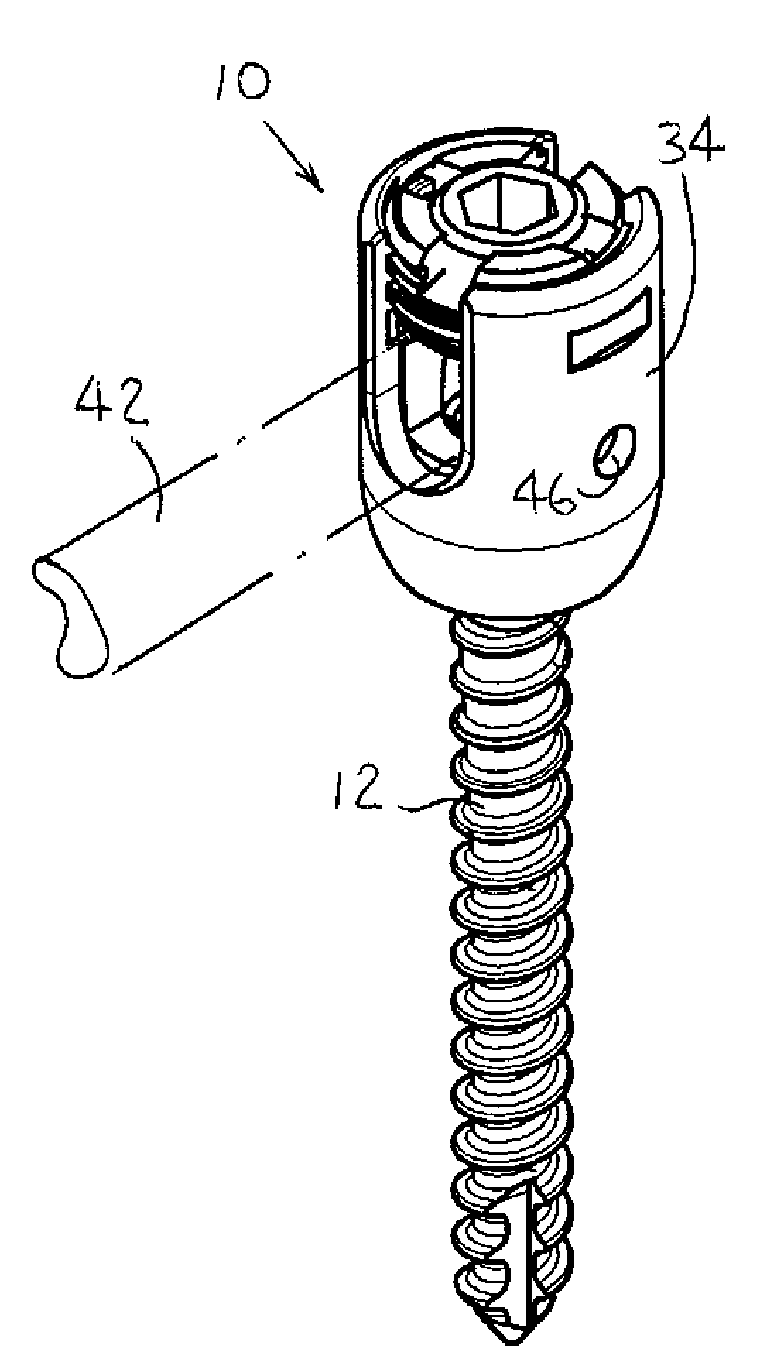
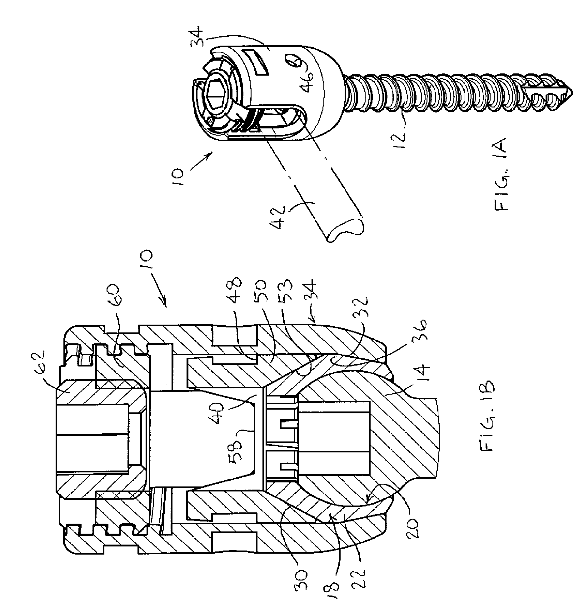
[0014]Reference is now made to FIGS. 1A-1B, which illustrate a connector assembly 10 for a bone anchoring element 12, constructed and operative in accordance with an embodiment of the present invention.

[0015]In a non-limiting embodiment of the invention, the bone anchoring element 12 includes a threaded mechanical fastener (for example, without limitation, a pedicle screw, a pedicle anchor device, a blocking screw for a pedicle anchoring device or any other device for attachment to the pedicle, vertebral body or any other bone) having a spherical proximal portion 14 (also referred to as a spherical head 14) and a (pointed) distal portion 16. Alternatively, bone anchoring element 12 can be a hook or other mechanical fastener with a spherical head. The spherical head 14 may be formed with a socket for an Allen wrench or the like.

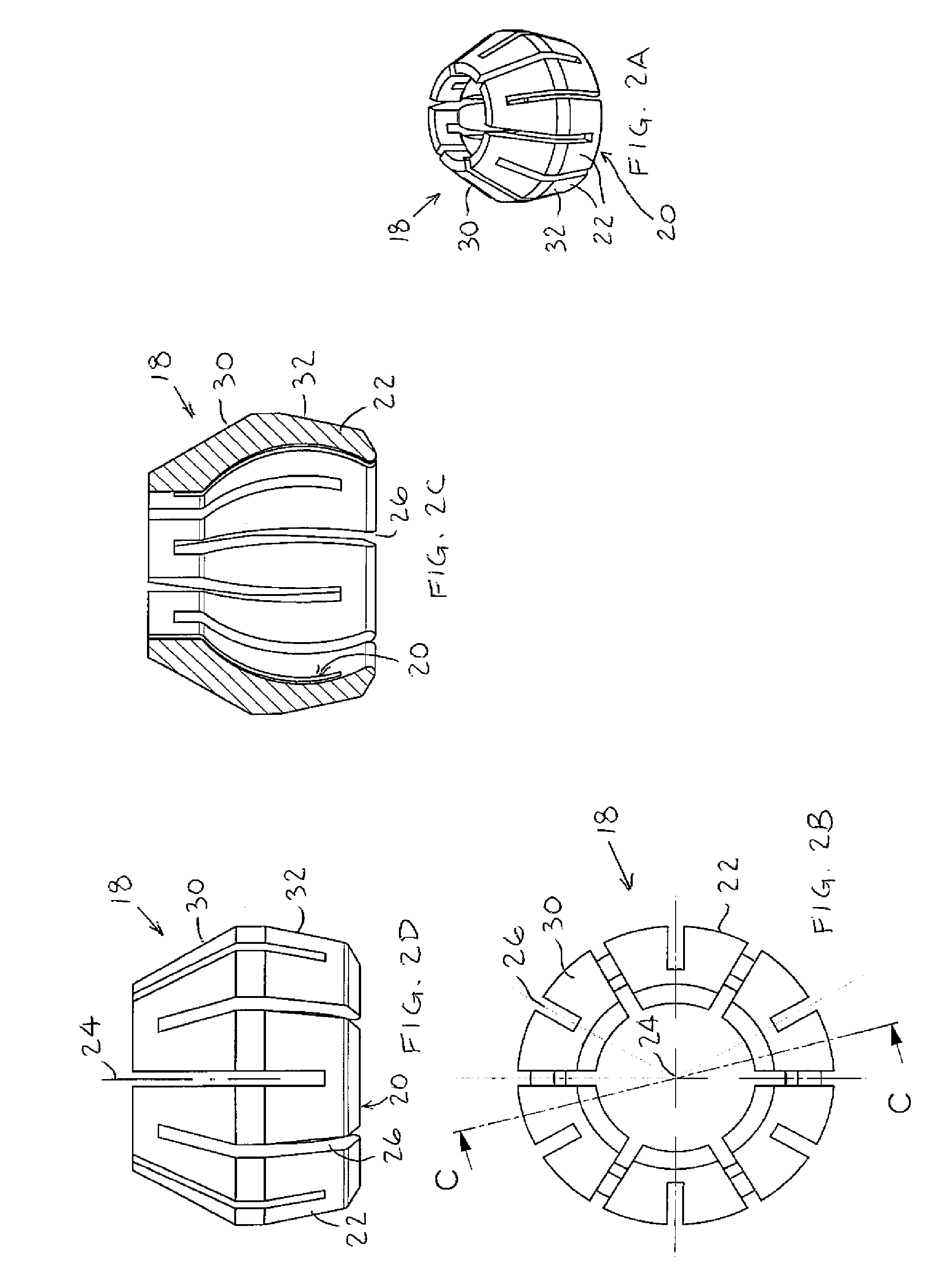
[0016]Reference is now made additionally to FIGS. 2A-2D. The connector assembly 10 includes a double collet 18 that includes an inner clamping portion 20, for...


PUM


Abstract

A connector assembly including a bone anchoring element including a spherical head, a double collet that includes an inner clamping portion formed by inner surfaces of a plurality of resilient fingers, the resilient fingers defining a first wedge surface and a second wedge surface, an outer closure element that includes an inner clamping portion that corresponds in shape to an outer contour of the double collet, the outer closure element including a pair of arms that define a channel shaped for receiving therein a connector element, and an interface ring that includes a base formed with an inner wedge surface and a pair of wing extensions that extend from the base.

Description

FIELD OF THE INVENTION[0001]The present invention relates generally to anchoring structures for orthopedic devices, and particularly to a connector assembly for connecting rods and the like to bone anchoring elements, such as pedicle screws.BACKGROUND OF THE INVENTION[0002]Many spinal fixation systems are found in the prior art for fixing connecting rods and the like to pedicle screws. Some systems have a disadvantage in that the rod must be bent after coupling to the pedicle screw because of anatomical considerations. Some systems attempt to solve this problem with different kinds of connectors that secure the rod to a polyaxial pedicle screw head and permit spatial adjustments before locking the rod in place. It is imperative to lock the connecting rod with respect to the pedicle screw (or any other kind of bone anchoring element) in order to prevent loosening of the spinal fixation system that could have undesirable consequences to the patient. Nevertheless, no design is free of ...

Claims


Application Information

Patent Timeline
Patent Type & Authority Patents(United States)
IPC IPC(8): A61B17/04A61B17/70
CPCA61B17/7032A61B17/7037
Inventor LEVY, MARK M.ZYLBERBERG, EYALSPANIER, YAIR
Owner EXPANDING ORTHOPEDICS
Why Eureka
Try Eureka