Spinal stabilization device with weld cap

a technology of spinal stabilization device and weld cap, which is applied in the direction of osteosynthesis device, prosthesis, manufacturing tools, etc., can solve the problems of accelerating degeneration at those levels, resilient elements developing significant internal stress levels, and reducing range of motion, so as to promote reliable and effective spinal stabilization

Inactive Publication Date: 2010-04-20
RACHIOTEK
View PDF93 Cites 119 Cited by
  • Summary
  • Abstract
  • Description
  • Claims
  • Application Information

AI Technical Summary

Benefits of technology

[0008]According to the present disclosure, advantageous devices, systems and methods for spinal stabilization are provided. According to exemplary embodiments of the present disclosure, the disclosed devices, systems and methods include a spring junction that promotes reliable and efficacious spinal stabilization. The disclosed spring junction includes a structural member that is mounted or mountable with respect to a spine attachment fastener, such as a pedicle screw, and a resilient element, e.g., a spring, affixed with respect to the structural member.
[0009]According to the present disclosure, a weld cap is configured and dimensioned to interact with the resilient element and the structural member so as to securely position the resilient element relative to the structural member. Moreover, the weld cap functions to advantageously distance the welding process and associated welding energy from the resilient element, thereby avoiding and / or minimizing any potentially undesirable annealing effect associated with securing / welding the resilient element relative to the structural member. According to exemplary embodiments of the present disclosure, a first weld cap interacts with the resilient element at a first end region thereof, and a second weld cap interacts with the resilient element at a second end region thereof, thereby effectively securing the resilient element with respect to opposed structural members at either end of an elongated spinal stabilization device.
[0010]According to exemplary embodiments of the present disclosure, the spring junction includes a weld region wherein the weld cap is affixed to an underlying structural member. The weld cap and the underlying structural member are advantageously configured and dimensioned to interact with the resilient element such that the resilient element is positioned in a predefined location. For example, an exemplary weld cap and structural member according to the present disclosure include opposed channels or grooves that are sized and oriented to receive the resilient element therewithin. In this way, the resilient element is properly and effectively aligned during the assembly process, and is fixed between the weld cap and the structural member upon welding of the weld cap with respect to the structural member. Indeed, according to exemplary embodiments of the present disclosure, the resilient element is captured between the weld cap and the structural member and maintained in a fixed orientation relative to the weld cap / structural member assembly due to compressive forces exerted therebetween. Additionally, one or both cooperating surfaces of the weld cap / structural member may be subjected to surface treatment(s), e.g., grip blasting, to enhance the frictional force exerted between such surface(s) and the resilient element.

Problems solved by technology

While fusion is effective about seventy percent of the time, there are consequences even to these successful procedures, including a reduced range of motion and an increased load transfer to adjacent levels of the spine, which may accelerate degeneration at those levels.
Further, a significant number of back-pain patients, estimated to exceed seven million in the U.S., simply endure chronic low-back pain, rather than risk procedures that may not be appropriate or effective in alleviating their symptoms.
While the flexibility afforded by such resilient elements is plainly critical to the effectiveness of the respective devices of which they form a part, the elevated force levels associated with the use of such resilient elements can result in such resilient elements developing significant levels of internal stress.
Depending on the magnitude and location thereof, internal stresses may pose the potential for stress-induced fatigue, material deformation and / or cracks.

Method used


Image

  • Spinal stabilization device with weld cap
  • Spinal stabilization device with weld cap
  • Spinal stabilization device with weld cap

Examples


Embodiment Construction

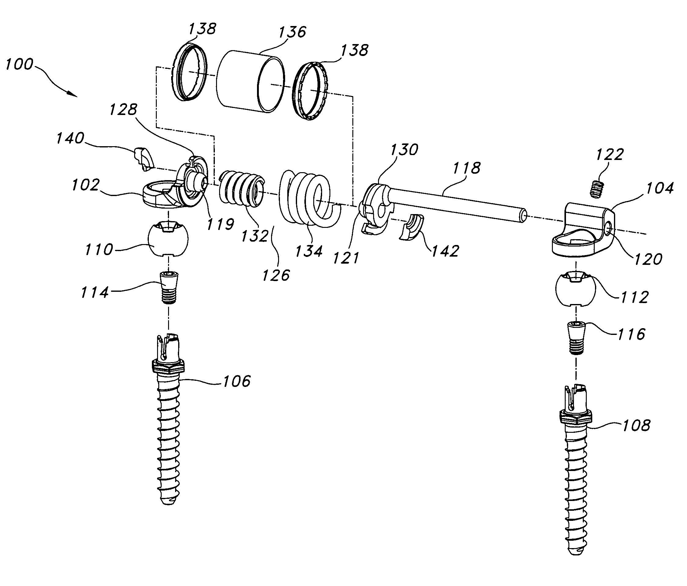
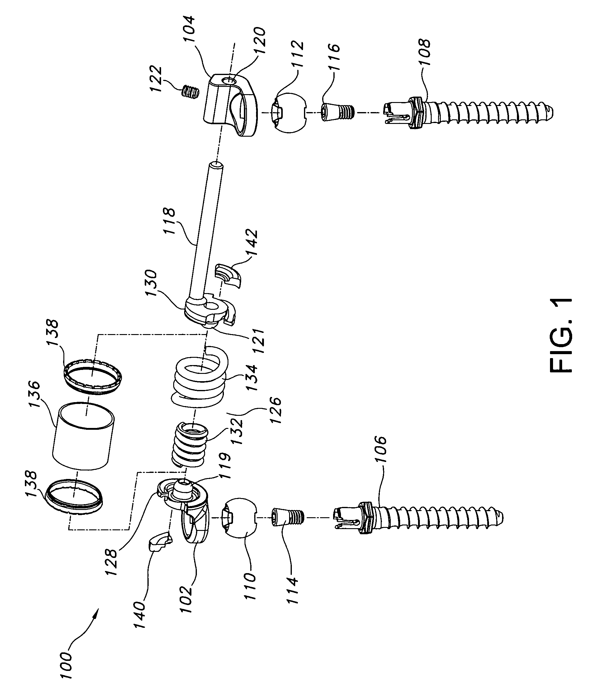
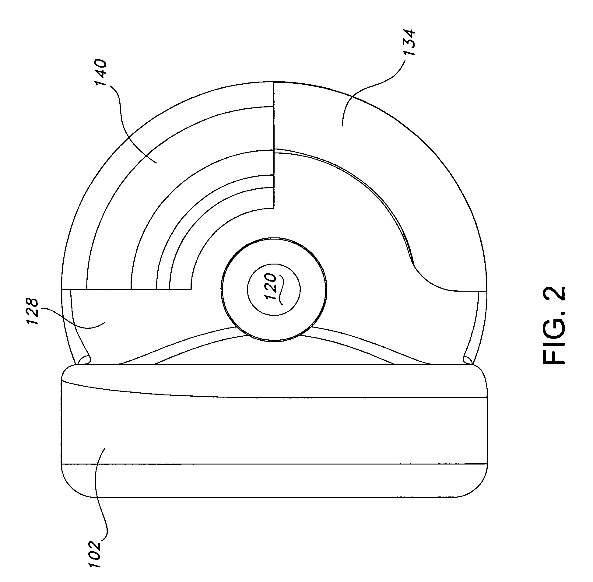
[0032]The present disclosure provides advantageous devices, systems and methods for improving the reliability, dependability and / or durability of spinal stabilization systems. More particularly, the present disclosure provides advantageous devices, systems and methods for mechanically mounting resilient elements (e.g., torsion springs and / or coil springs) to, and / or for coupling resilient elements between, structural members (e.g., plates, caps, flanges, rods, and / or bars) associated with dynamic spinal stabilization systems. The mounting and / or coupling methods / techniques of the present disclosure provide enhanced reliability, dependability and / or durability without significantly increasing material weight or volume requirements and without compromising the important functions of the dynamic spinal stabilization devices / systems of which they form a part.

[0033]The exemplary embodiments disclosed herein are illustrative of the advantageous spinal stabilization devices / systems and sur...


PUM

PropertyMeasurementUnit
temperaturesaaaaaaaaaa
heightaaaaaaaaaa
heightaaaaaaaaaa

Abstract

A weld cap is configured and dimensioned to interact with a resilient element, e.g., a spring, and a structural member, e.g., an end cap, so as to securely position the spring relative to the end cap. The weld cap functions to distance the welding process and associated welding energy from the spring, thereby avoiding and / or minimizing any potentially undesirable annealing effect associated with securing / welding the spring relative to the end cap. A first weld cap interacts with the spring at a first end region thereof, and a second weld cap interacts with the spring at a second end region thereof, thereby effectively securing the spring with respect to opposed end caps at either end of an elongated spinal stabilization device. Alignment grooves or channels may be provided for orienting or aligning the spring with respect to the end caps and weld caps. The end regions of the spring may also include bend regions that facilitate the assembly process and / or further minimize the freedom of movement of the spring relative to the end cap / weld cap combination. The dynamic stabilization device and associated system provide advantageous clinical results in spinal applications.

Description

BACKGROUND[0001]1. Technical Field[0002]The present disclosure is directed to a spinal stabilization device / system that includes at least one spring member and at least one weld cap to facilitate secure interaction of the spring member with other structural components of the spinal stabilization device / system.[0003]2. Background Art[0004]Each year, over 200,000 patients undergo lumbar fusion surgery in the United States. While fusion is effective about seventy percent of the time, there are consequences even to these successful procedures, including a reduced range of motion and an increased load transfer to adjacent levels of the spine, which may accelerate degeneration at those levels. Further, a significant number of back-pain patients, estimated to exceed seven million in the U.S., simply endure chronic low-back pain, rather than risk procedures that may not be appropriate or effective in alleviating their symptoms.[0005]New treatment modalities, collectively called motion prese...

Claims


Application Information

Patent Timeline
Patent Type & Authority Patents(United States)
IPC IPC(8): A61B17/70
CPCA61B17/7007B23K33/00A61B17/7028A61B17/7004A61B17/7041A61B17/7011
Inventor TIMM, JENS P.
Owner RACHIOTEK
Why Eureka
Try Eureka