Extending and retracting device and vehicle step apparatus with the same

a vehicle step and extending device technology, applied in the direction of vehicle components, steps arrangement, transportation and packaging, etc., can solve the problems of difficult to meet ground clearance and convenience requirements simultaneously with a conventional vehicle step, the operation of the retractable vehicle step is not reliable, and the level does not provide sufficient ground clearance during the operation of many vehicles. , to achieve the effect of long useful life of the vehicle step apparatus, and convenient extending and retracting action

Active Publication Date: 2011-10-25
HANGZHOU TIANMING TECH CO LTD
View PDF76 Cites 59 Cited by
  • Summary
  • Abstract
  • Description
  • Claims
  • Application Information

AI Technical Summary

Benefits of technology

[0010]One advantage of the vehicle step apparatus of the present invention is that it employs a five-link mechanism, is reliable and stable with a long operational life, does not increase cost, and eliminates interference occurring between the two extending and retracting devices.
[0017]Another advantage of the vehicle step apparatus of the present invention is that it distributes stress evenly with a buffering structure that is structurally simple and is relatively lightweight and more aesthetically pleasing.

Problems solved by technology

In terms of ergonomics, the vehicle step is generally mounted at a level of 15 cm with respect to the ground so that it is convenient for the passenger to get on or off it, but this level does not provide sufficient ground clearance during operation of many vehicles.
Therefore, it is difficult to meet ground-clearance and convenience requirements simultaneously with a conventional vehicle step.
Since the pair of four-link mechanisms is driven by one motor, a driving force applied to the retractable vehicle step is not balanced, and rotations of two four-link mechanisms of the retractable vehicle step are not synchronous so that operation of the retractable vehicle step is not reliable.
If a conventional four-link retractable vehicle step employs two motors to drive the two four-link mechanisms simultaneously, rotations of the two motors and / or four-link mechanisms may not be synchronous so that the four-link mechanisms may interfere with each other.
The retractable vehicle step may be destroyed due to the interference and fail to operate.
Furthermore, in a conventional vehicle step apparatus, a distance between two pivot shafts connecting the four-link mechanism with the step member is short so that stress tends to concentrate on respective positions of the pivot shafts when a passenger steps on an extended step member.
Thus, the pivot shafts tend to be destroyed over time due to their lack of mechanical strength.
Therefore, reliability is reduced, and cost is increased.

Method used


Image

  • Extending and retracting device and vehicle step apparatus with the same
  • Extending and retracting device and vehicle step apparatus with the same
  • Extending and retracting device and vehicle step apparatus with the same

Examples


first embodiment

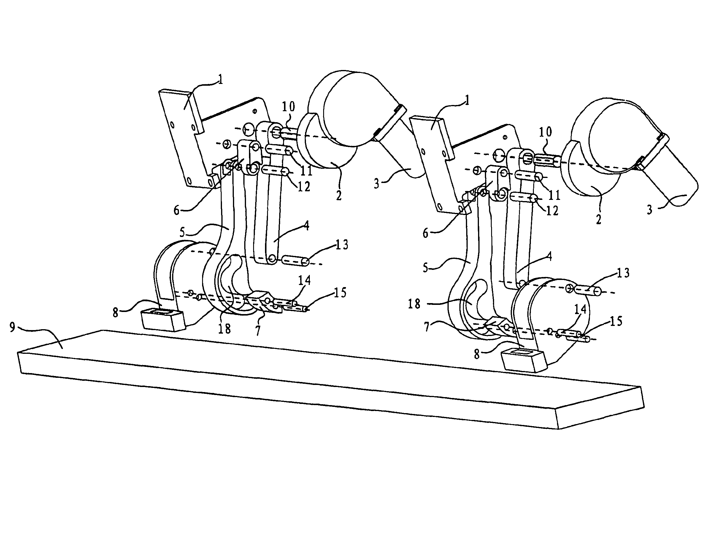
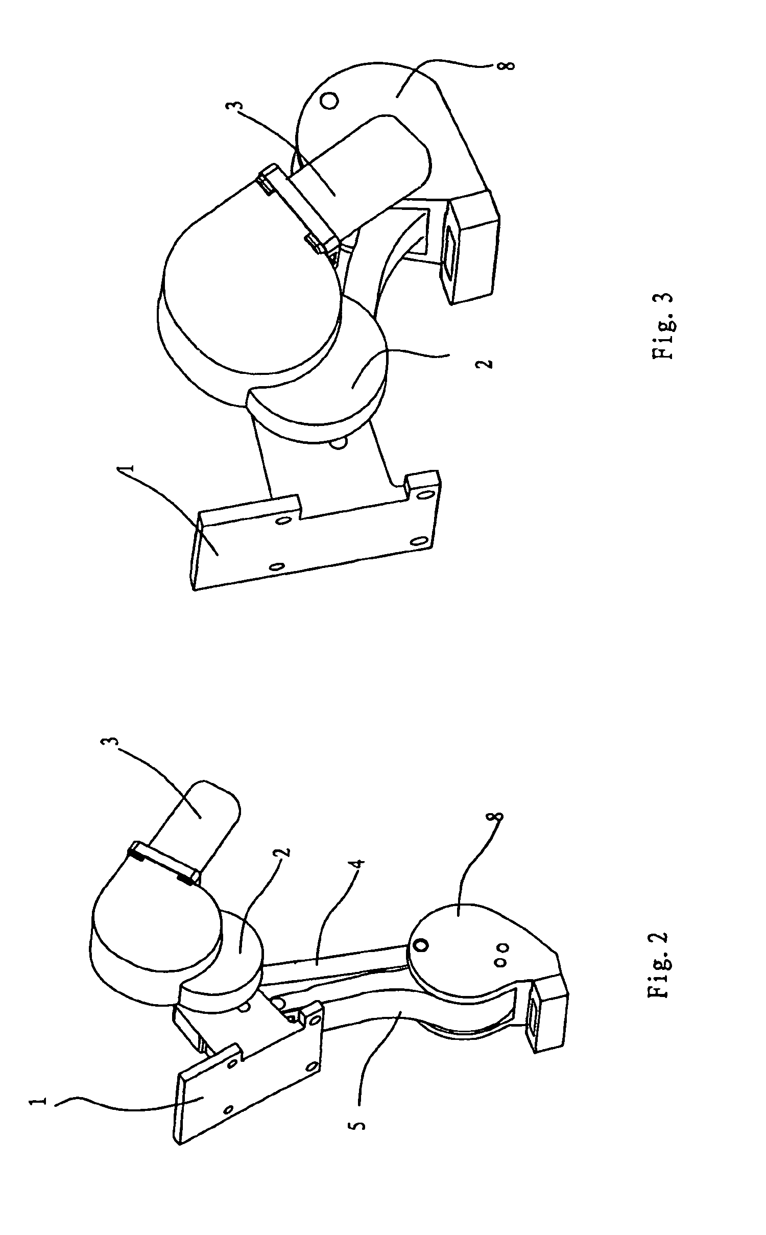
[0045]In operation of the first embodiment and as shown in FIGS. 2 and 3, when it is required to move the extending and retracting device from the extended state (as shown in FIG. 2) to the retracted state (as shown in FIG. 3), the reversible motor 3 rotates the first arm 4 in counterclockwise direction (as viewed in FIG. 3) with respect to the mounting bracket 1 via the speed reducer 2, thus driving the second arm 5 and third arm 6 to rotate with respect to the mounting bracket 1. When the second arm 5 rotates, the arc-sliding member 7 slides in the arc slot 18 so that the step bracket 8 moves upwardly and rearwardly with respect to the mounting bracket 1. In this way, the extending and retracting device moves to the retracted state (as shown in FIG. 3). Through reversed rotation of the motor 3, the extending and retracting device can move from the retracted state (as shown in FIG. 3) to the extended state (as shown in FIG. 2).

[0046]It should be appreciated by those having ordinary...

third embodiment

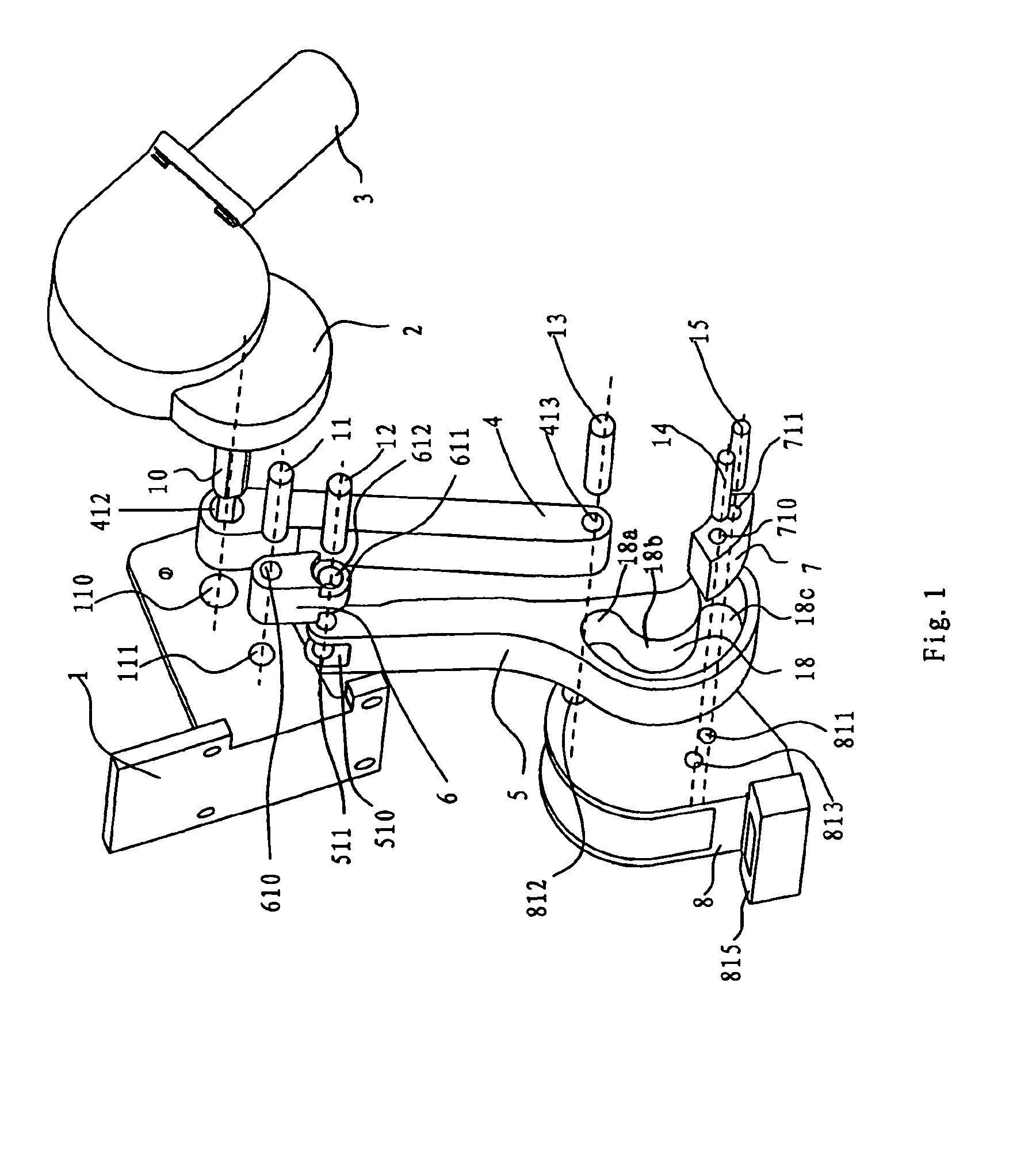
[0050]In the third embodiment, the mounting bracket 1 is formed with a recess 112, and the respective upper end portions of the third arm 6 and first arm 4 are inserted into the recess 112 and pivotably connected to the mounting bracket 1 via corresponding pins 11, 10. The lower end portion of the first arm 4 is formed with groove 411. The lower end portion of the second arm 5 is formed with groove 512. The step bracket 8 is inserted into grooves 411, 512.

[0051]A pair of side walls are formed in the step bracket 8, and the arc-sliding member 7 is mounted onto the step bracket 8 and extended laterally and outwardly into the arc slot 18 from the side walls. In particular, the step bracket 8 is formed with through-hole 814, and the arc-sliding member 7 is received in through-hole 814 and mounted onto the step bracket 8 such that both ends of the arc-sliding member 7 are extended laterally into the arc slot 18 located at both sides of groove 512. Since the lower end portion of the secon...

fourth embodiment

[0053]In the fourth embodiment, the upper end portion of the third arm 6 is formed with groove 613, the upper end portion of the first arm 4 is formed with groove 410, and the lower end portion of the first arm 4 is formed with groove 411. The mounting bracket 1 is inserted into grooves 613, 410 and pivotably connected to the third arm 6 and first arm 4 via corresponding pins 11, 10.

[0054]The lower end portion of the second arm 5 is formed with groove 512, and the step bracket 8 is inserted into groove 512. The arc-sliding member 7 includes a first arc-sliding member 7a and a second arc-sliding member 7b. The step bracket 8 is formed with through-holes 811, 812, 813. The first arc-sliding member 7a is formed with through-holes 711a, 712a, and the second arc-sliding member 7b is formed with screw holes 711b, 712b. As shown in FIG. 7, the first arc-sliding member 7a and second arc-sliding member 7b are mounted respectively to the pair of side walls of the step bracket 8 via bolts 16, ...


PUM


Abstract

An extending and retracting device for a vehicle step includes a mounting bracket adapted to be fixed to a vehicle body and a step bracket adapted to be connected to a step member of the vehicle step. First and second arms each defines a lower end portion connected to the step bracket and an upper end portion. A third arm defines an upper end portion rotatably connected to the mounting bracket and a lower end portion rotatably connected to the upper end portion of the first or second arm. The upper end portion of the other of the first or second arm is rotatably connected to the mounting bracket. At least one arc-sliding member is mounted to the step bracket. At least one arc slot is formed in the lower end portion of the second arm. The arc-sliding member is adapted to fit into the corresponding arc slot so as to be slidable in the arc slot so that the lower end portion of the second arm is rotatable with respect to the step bracket.

Description

BACKGROUND OF THE INVENTION[0001]1. Field of the Invention[0002]The present invention relates, generally, to a vehicle body and, more particularly, to an extending and retracting device for a step of the vehicle body.[0003]2. Description of the Related Art[0004]A step under a door of a vehicle is used for a passenger to get on or off the vehicle. In terms of ergonomics, the vehicle step is generally mounted at a level of 15 cm with respect to the ground so that it is convenient for the passenger to get on or off it, but this level does not provide sufficient ground clearance during operation of many vehicles. The level of the vehicle step should be higher than ground clearance of the vehicle. Therefore, it is difficult to meet ground-clearance and convenience requirements simultaneously with a conventional vehicle step.[0005]U.S. Pat. No. 6,830,257 discloses a retractable vehicle step employing a four-link mechanism. When a door of a vehicle is opened, the vehicle step is automatica...

Claims


Application Information

Patent Timeline
Patent Type & Authority Patents(United States)
IPC IPC(8): B60R3/00B60R3/02
CPCB60R3/02
Inventor YANG, HUIZHONGYANG, LINGLING
Owner HANGZHOU TIANMING TECH CO LTD
Why Eureka
Try Eureka