Time domain radio transmission system

a radio transmission system and time domain technology, applied in the field ofsignal transmission systems, can solve the problems of prolonging the length of a signal burst, adversely affecting the coupling of signals to the antenna, interfering with the signal radiated, etc., and achieve the effect of convenient frequency modulation

Inactive Publication Date: 2007-08-07
TIME DOMAIN
View PDF88 Cites 91 Cited by
  • Summary
  • Abstract
  • Description
  • Claims
  • Application Information

AI Technical Summary

Benefits of technology

[0022]Finally, and of very substantial significance, is that the light modulator referred to the preceding paragraph provides what is believed to be a breakthrough in conveniently enabling frequency modulation of light signals passing, for example, through a fiber optic having a variable refractive index with bias voltage. Additionally, it may be employed as a selectable delay device.

Problems solved by technology

As a further consideration, practical power restraints in the past have been generally limited to the application of a few hundred volts of applied signal energy to the transmitting antenna.
In this manner, no metallic triggering communications line extends to the antenna which might otherwise pick up radiation and re-radiate it, adversely effecting signal coupling to the antenna and interfering with the signal radiated from it, both of which tend to prolong the length of a signal burst, a clearly adverse effect.

Method used


Image

  • Time domain radio transmission system
  • Time domain radio transmission system
  • Time domain radio transmission system

Examples


Embodiment Construction

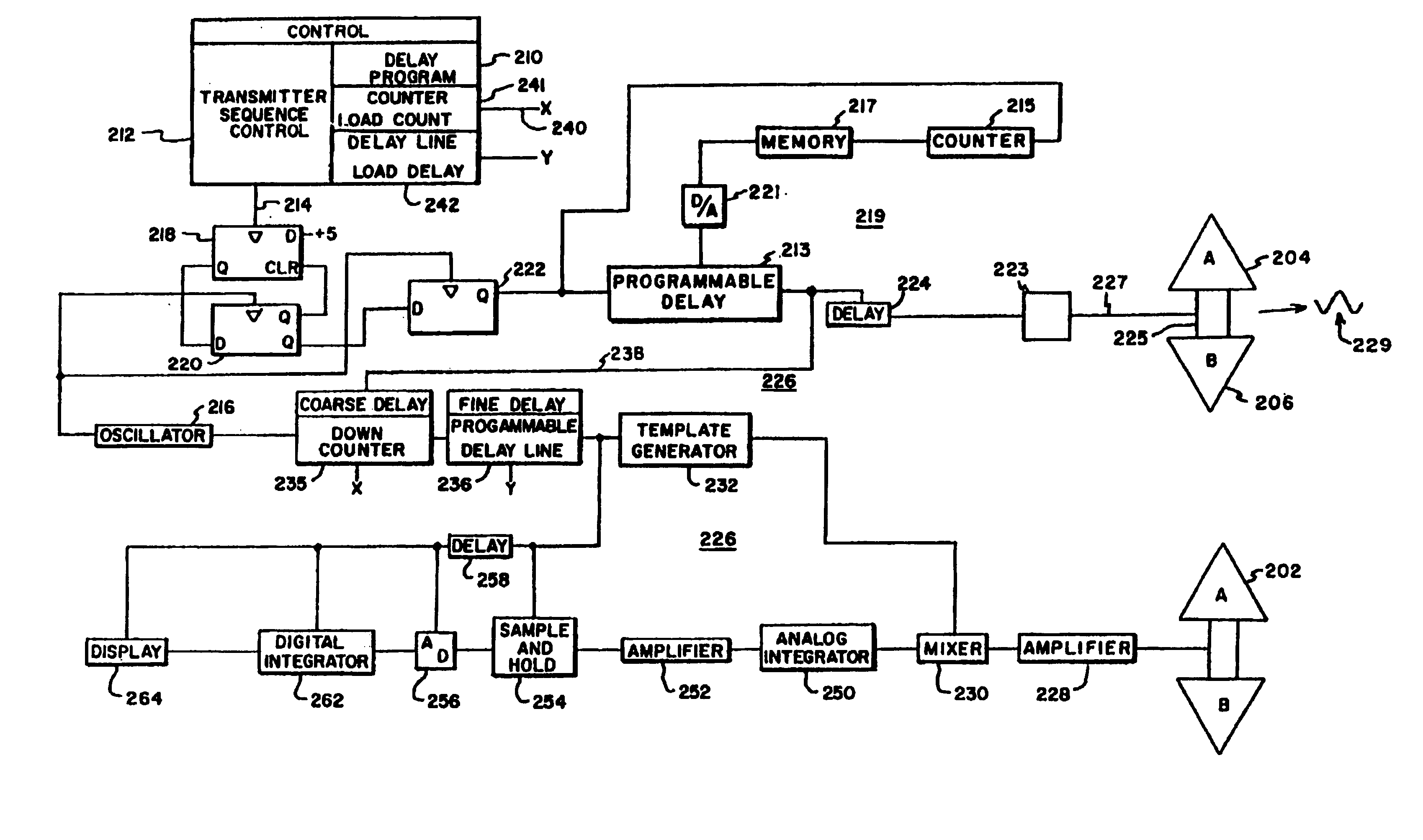
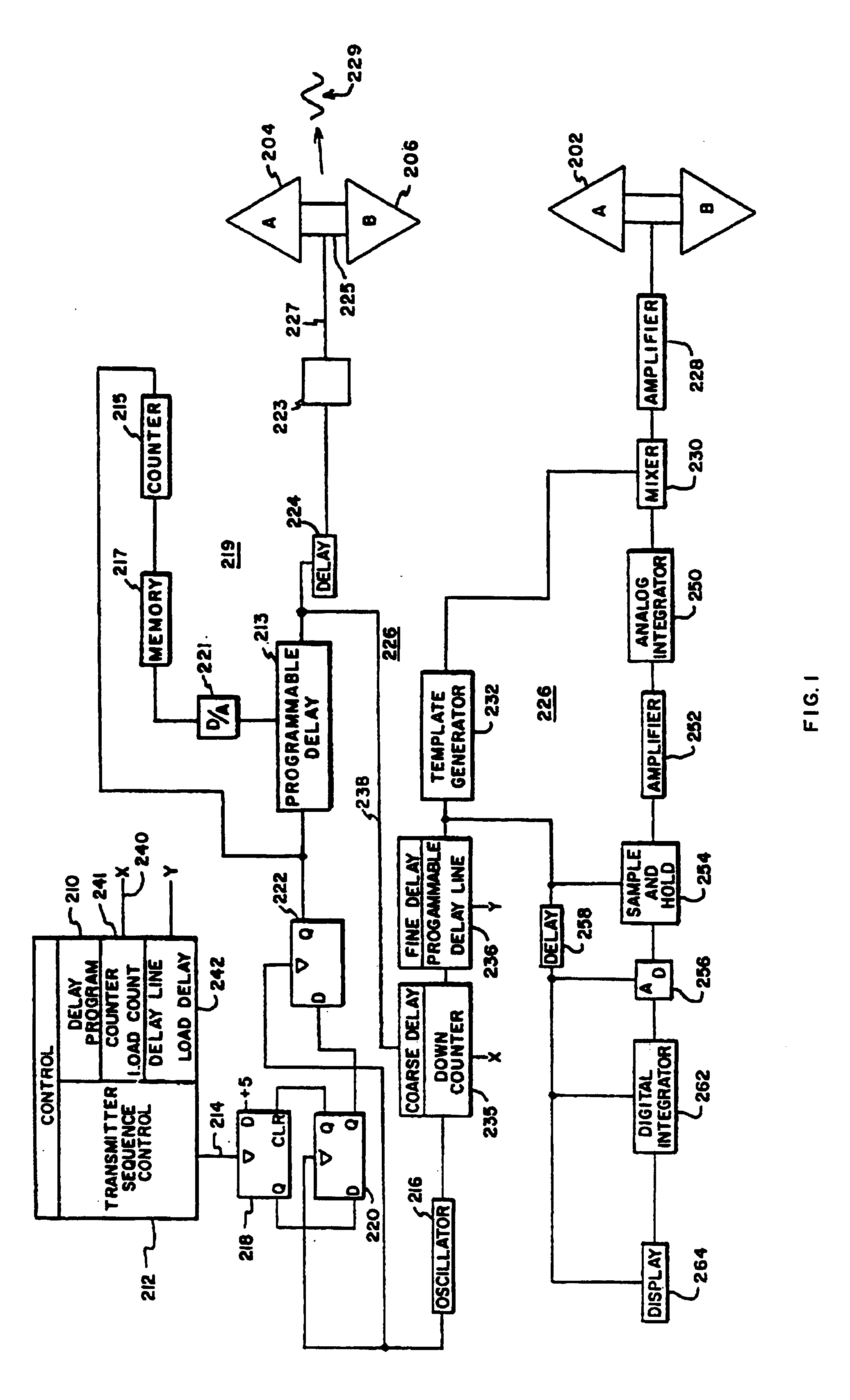
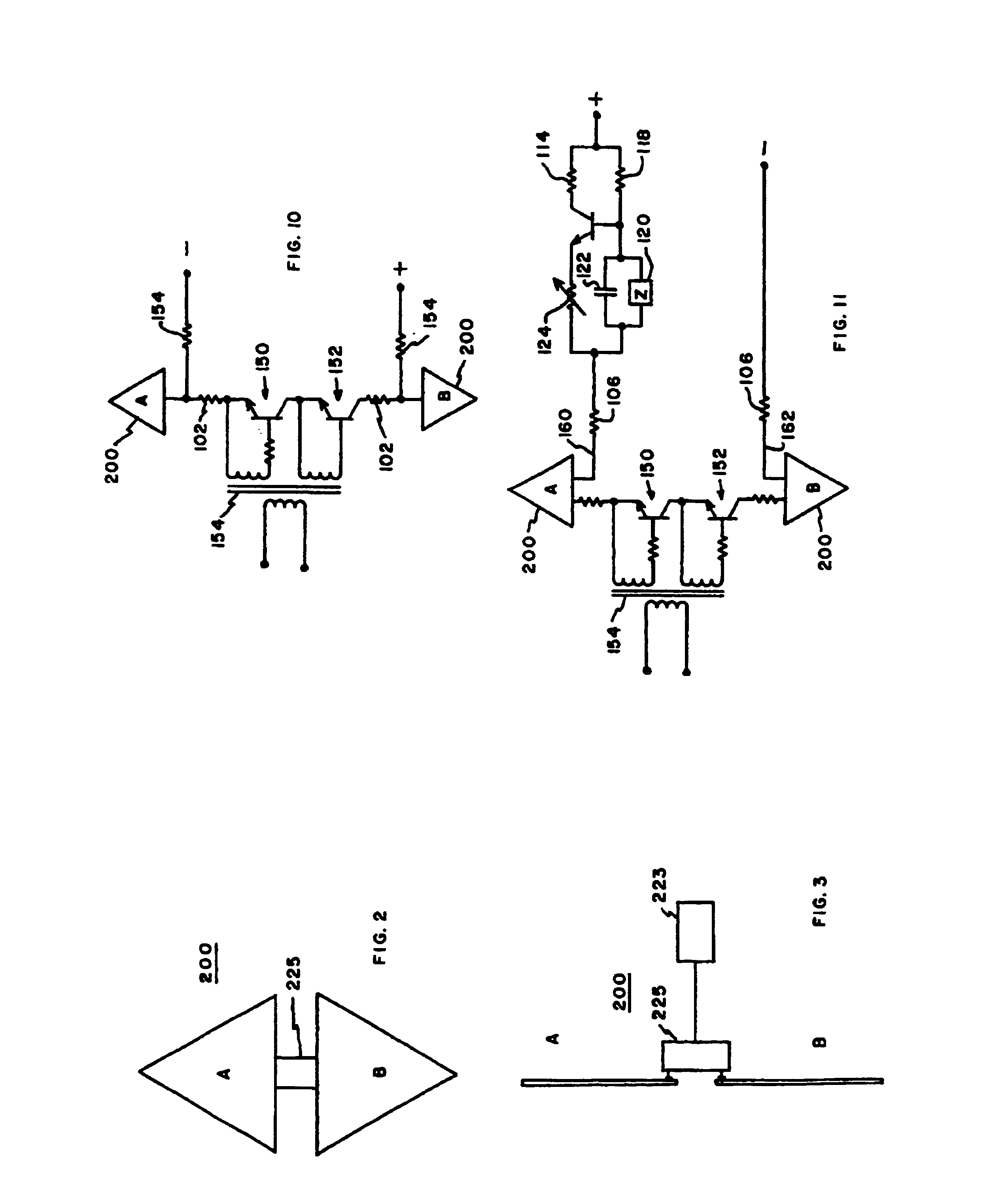
[0031]Referring to the drawings, FIG. 1 particularly illustrates a radar application of the present invention for determining range. Transmitting antenna 200 of transmitter 219 is a conformal reverse bicone, but flat, antenna having triangular elements A and B with closely spaced, 0,050 inches, bases. A dimension of an element normal to the base is approximately 4½ inches and is further discussed and illustrated in FIGS. 2 and 3. Typically, a reflector would be used as illustrated in FIG. 4.

[0032]The transmitter is basically controlled by control 210. It includes a transmit sequence control portion 212 which determines the timing of transmitted signal bursts, at, for example, 10,000 bursts per second, in which case transmit sequence control 212 generates an output at 10,000 Hz on lead 214. Oscillator 216 is operated at a higher rate, for example, 20 MHz.

[0033]The signal output of transmit sequence control 212 is employed to select particular pulse outputs of oscillator 216 to be the...


PUM


Abstract

A time domain communications system wherein a broadband of time-spaced signals, essentially monocycle-like signals, are derived from applying stepped-in-amplitude signals to a broadband antenna, in this case, a reverse bicone antenna. When received, the thus transmitted signals are multiplied by a D.C. replica of each transmitted signal, and thereafter, they are, successively, short time and long time integrated to achieve detection.

Description

[0001]This application is a continuation of application Ser. No. 07 / 368,831, filed on Jun. 20, 1989; which is a continuation-in-part of application Ser. No. 07 / 192,475, filed on May 10, 1988; which is a continuation-in-part of application Ser. No. 06 / 870,177, filed on Jun. 3, 1986, now U.S. Pat. No. 4,743,906; which is a continuation-in-part of application Ser. No. 06 / 677,597, filed on Dec. 3, 1984, now U.S. Pat. No. 4,641,317.[0002]This application is also a continuation-in-part of International Application No. PCT / US90 / 01174, filed on Mar. 2, 1990, which is a continuation-in-part of International Application No. PCT / US89 / 01020, filed on Mar. 10, 1989. Said PCT Application No. PCT / US89 / 01020 is also a continuation-in-part of U.S. application Ser. No. 07 / 010,440, filed on Feb. 3, 1987, now U.S. Pat. No. 4,813,057.FIELD OF THE INVENTION[0003]This invention relates generally to signal transmission systems, and particularly to a time domain system wherein spaced narrow signal bursts, i...

Claims


Application Information

Patent Timeline
Patent Type & Authority Patents(United States)
IPC IPC(8): G01S13/04H04L27/30G01S7/282G01S7/292G01S13/02G01S13/18H01Q9/28H01Q21/06H04B1/7163H04B1/717H04B1/719H04B14/02
CPCG01S7/282G01S7/292G01S13/0209G01S13/18H01Q9/28H01Q21/061H04B1/71632H04B1/71637H04B1/7174H04B1/719H04B14/026H04L27/103
Inventor FULLERTON, LARRY W.
Owner TIME DOMAIN
Why Eureka
Try Eureka