
Table, especially office and conference table

a technology for tables and chairs, applied in the field of tables, can solve the problems of restricting design freedom and increasing the cost of tables

Inactive Publication Date: 2006-05-11
VITRA PATENTE AG
View PDF9 Cites 65 Cited by
  • Summary
  • Abstract
  • Description
  • Claims
  • Application Information

AI Technical Summary

Benefits of technology

[0003] In view of the previous disadvantages in the structural design of known tables, the object of the invention is to propose a table having reliable stability even in the case of relatively large dimensions, in particular in the case of a relatively long construction. The intention here is for the substructure used to be able to be produced in a relatively simple manner and to be less costly and use less material and not to unduly increase the overall weight. A further object of the invention is to be able to attach the legs to the table at selectable positions and to enable the supplying and accommodating of electrical installations for the supply of power and connection of networked computers. An additional object is to propose an effective height-leveling means, which is practical in terms of handling and is visually unobtrusive, in the table legs in order to compensate for unevennesses in the standing surface. SUMMARY OF THE INVENTION
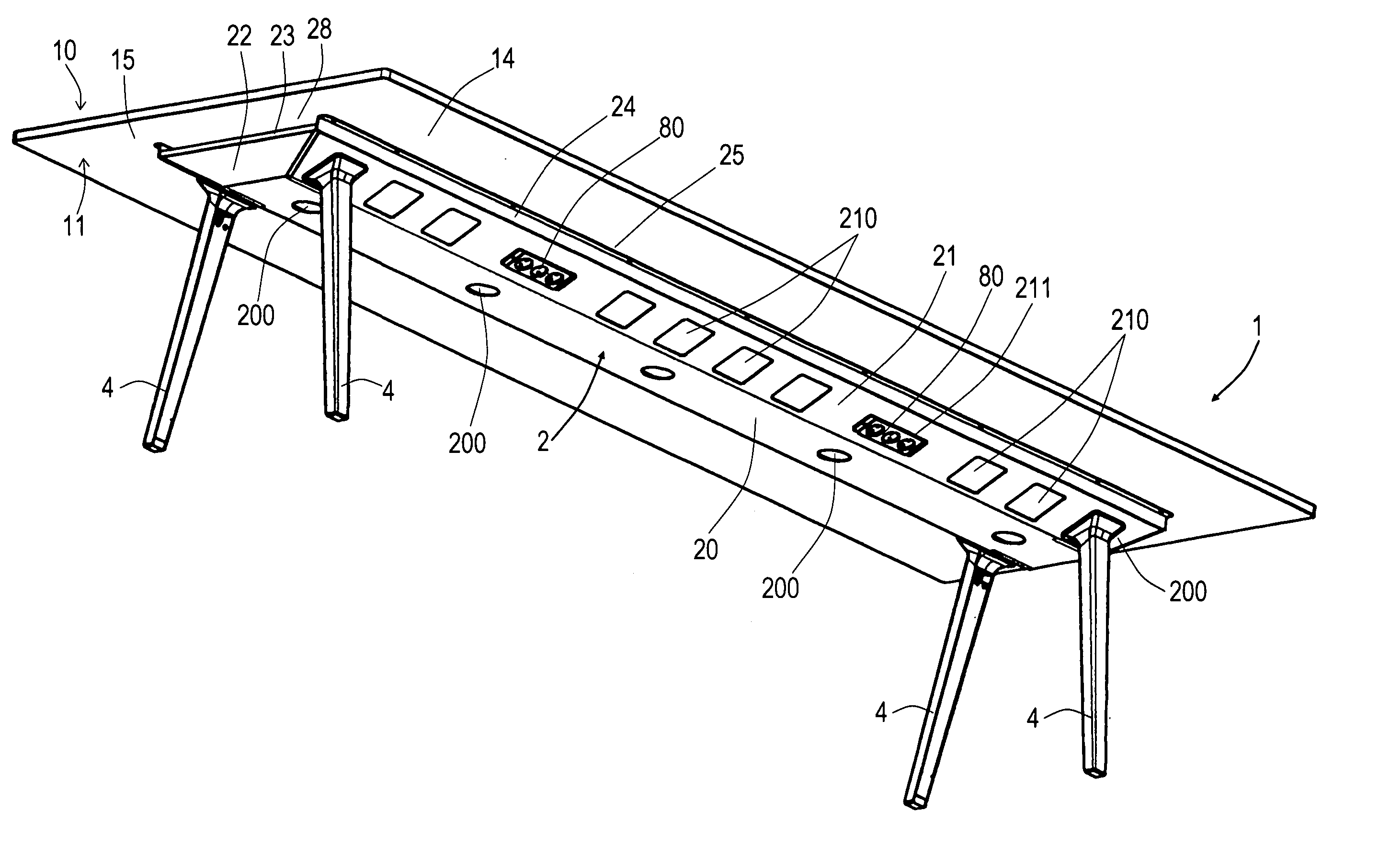
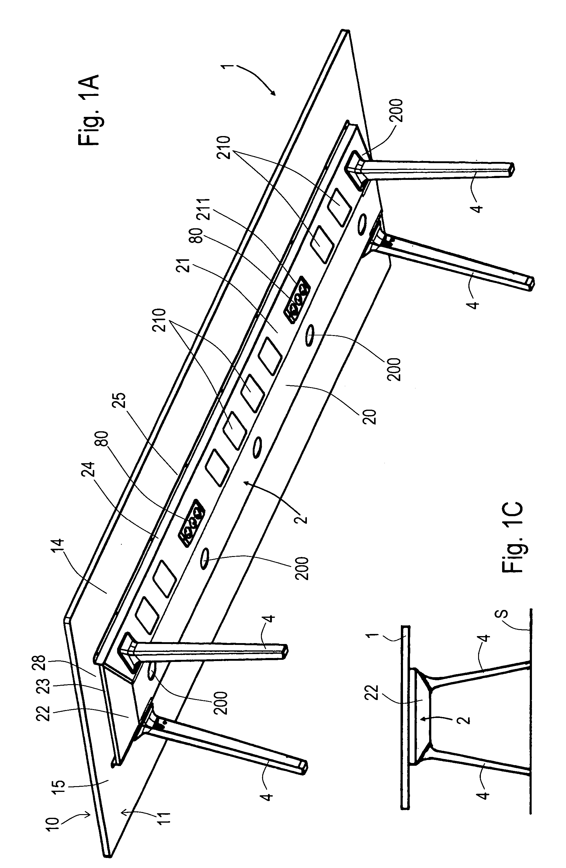
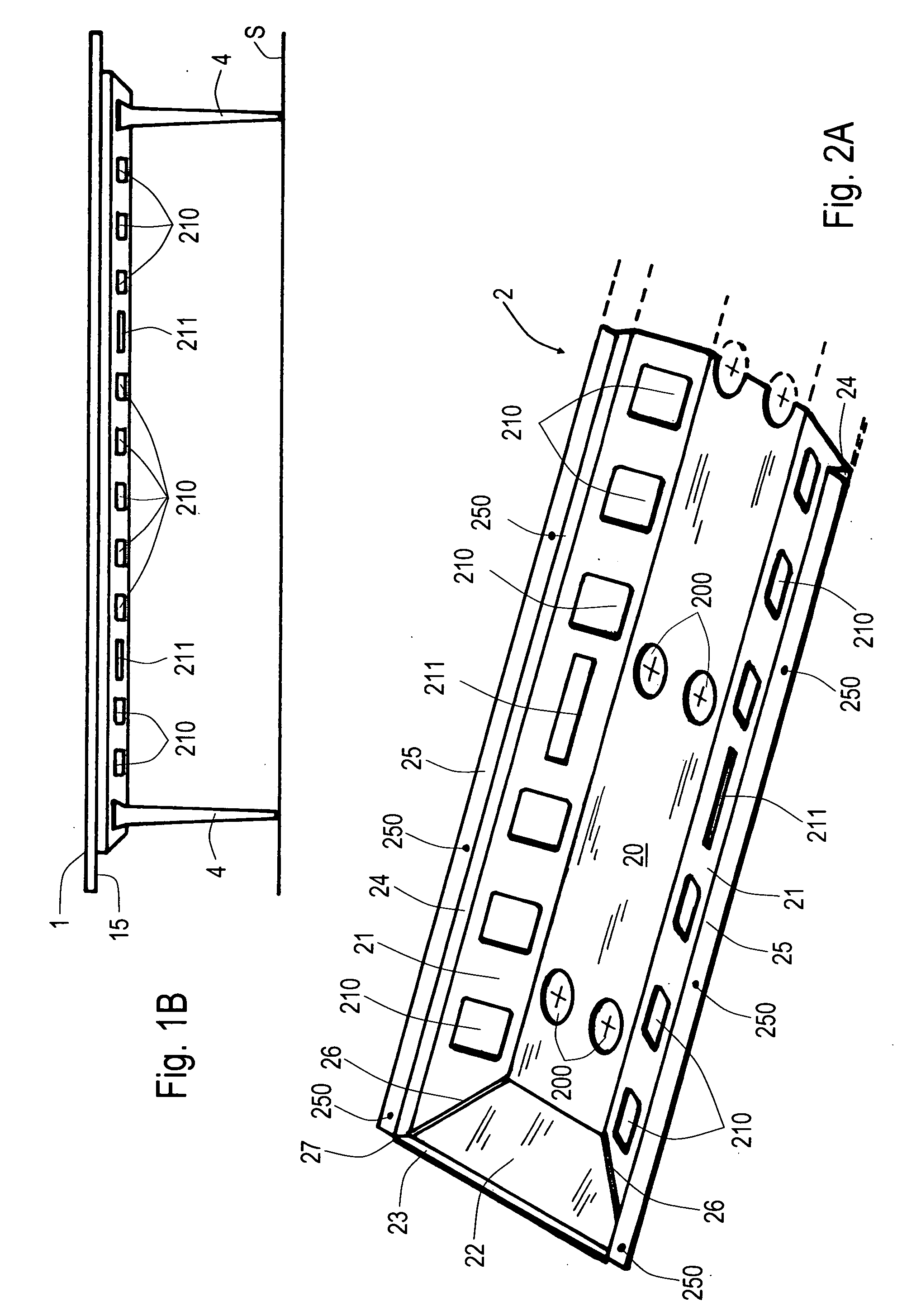
[0006] The trough has an average width which is a multiple of the height, for example the width is in the region of 50 cm and the height is in the region of 10 cm, resulting in a ratio of 5:1. For visual and ergonomic reasons, the tabletop protrudes in each case with a lateral projecting length over the trough arranged below it, and there can also be a respective front projecting length. The plane elements are present at least on the two opposite longitudinal sides of the trough. In the case of troughs of larger dimensions which are more square, it is advantageous to provide the plane elements on all sides. In the case of a V-shaped cross section, the trough has a trench line, which is situated right at the bottom, or otherwise has a base, from which a respective longitudinal flank extends to both sides, said longitudinal flanks merging in each case into an outwardly bent-over edge forming the plane elements. The base preferably consists of sheet metal which is, e.g., 2.0 mm thick. The fixed connections between the tabletop and the trough are preferably spot-type screw connections; however, they could also be adhesive gaps over the entire surface area.
[0012] The base element has a cross section which corresponds in principle to the clear internal cross section of the leg profile at the lower leg end. The set-down surface, which is situated right at the bottom of the base element, is an oblique plane which compensates for the oblique position of the leg portion with respect to the standing surface. The base element and the coupling element can together form an integral constructional unit. As an alternative to this, a separate coupling element, to which the slide rod is fastened at the top and the base element is fastened at the bottom, is fitted between the lower end of a slide rod and a base element. The coupling element, which is separate or is connected integrally to the base element, is arranged in the leg profile in a manner such that it can be displaced axially over a defined region. The leg profile has, in principle, a U-shaped cross section with a rear wall and the two side walls which are adjacent to the latter and lie opposite each other. For increased stability, the double legs are attached to the trough in such a manner that the two legs define a plane which points in the longitudinal direction of the table. A leg covering is provided for covering the open side lying opposite the rear wall.
[0021] The particular advantages of the table according to the invention reside essentially in the stability which is achieved, even in the case of a relatively long construction; this being achieved while using a substructure in the form of a large-size trough that can be produced relatively simply and is less costly and uses less material. Its interior volume, the grid of apertures for attaching the legs and the further installation apertures enable the supplying and accommodating of electrical devices and the optional positioning of the legs.

Problems solved by technology

This makes the tables more expensive, restricts the design freedom and generally requires the separate provision of cable ducts or cable clips for holding the electrical installations for supplying power and computer networking that are indispensable nowadays on office and conference tables.

Method used


Image

  • Table, especially office and conference table
  • Table, especially office and conference table
  • Table, especially office and conference table

Examples


Embodiment Construction

[0046] The detailed description of exemplary embodiments for the table according to the invention takes place below with reference to the accompanying drawings.

[0047] The following statement applies to the entire further description. If reference numerals are contained in a figure for the purpose of graphical unambiguity, but are not explained in the immediately associated text of the description, reference is made to where they have been mentioned in the preceding descriptions of the figures. In the interest of clarity, the repeated designation of components in the following figures is generally omitted if it can be seen unambiguously in the drawings that they involve “repeating” components.

FIGS. 1A to 3B

[0048] The elongate table which is shown comprises a substructure in the form of an upwardly open trough 2, which is arranged below the tabletop 1 and is supported by legs 4 placed on a standing surface S. The tabletop 1 is placed directly onto the trough 2 and is connected fixe...


PUM


Abstract

The invention relates to a table which is primarily used as an office or conference table, is longer than 2.5 m, and comprises an upwardly open trough (2) as a substructure which is arranged beneath the leaf (1) of the table and preferably consists of sheet metal which is e.g. 2 mm thick. The leaf of the table (1) is connected in a fixed manner to edges (25) which are bent away from the trough (2), creating a sandwich-type structure with mutual reinforcement of the leaf (1) of the table and the trough (2). Especially advantageously, the trough (2) has a trapezoidal cross-section. A grid of openings (210) in the trough (2) enables the feet (4) of the table to be mounted in any position. Additional appliance openings (211) are used to insert socket units (80), while installation openings (200) in the bottom (20) of the trough (2) as used as cable ducts. A height leveling device is provided in each foot (4). A particular advantage of the invention is the stability achieved with a relatively light structure, even for longer tables.

Description

FIELD OF APPLICATION OF THE INVENTION [0001] The present invention relates to a table of variable dimensions, in principle of square section or, in particular, of relatively long lengths, comprising a substructure, which is supported by legs standing on a standing surface, and a tabletop placed onto the substructure. The table is primarily used in the office and conference sector. This necessitates routing power supply and communication cables to the table and installing and accommodating them thereon. PRIOR ART [0002] Numerous designs of large-size tables are known. Sufficient stability of the tables, primarily in the case of relatively large dimensions, in particular in the case of a relatively long construction, is made possible only by means of relatively solid understructures with complicated, material-intensive and heavy frames, including the attaching of additionally supporting legs. This makes the tables more expensive, restricts the design freedom and generally requires the...

Claims


Application Information

Patent Timeline
Patent Type & Authority Applications(United States)
IPC IPC(8): A47B37/00A47B13/02
CPCA47B13/02A47B37/00A47B2037/005
Inventor BRAUNING, EGONBOUROULLEC, ERWANBOUROULLEC, RONAN
Owner VITRA PATENTE AG
Learn More