Vehicle step apparatus and extending and retracting device therefor

a technology of vehicle body and step, which is applied in the direction of vehicle components, steps arrangement, transportation and packaging, etc., can solve the problems of difficult to meet ground clearance and convenience requirements simultaneously with a conventional vehicle step, the operation of the retractable vehicle step is not reliable, and the level does not provide sufficient ground clearance during the operation of many vehicles. , to achieve the effect of reliable and stable operation, eliminating interference, and long operation li

Active Publication Date: 2011-11-08
HANGZHOU TIANMING TECH CO LTD
View PDF73 Cites 58 Cited by
  • Summary
  • Abstract
  • Description
  • Claims
  • Application Information

AI Technical Summary

Benefits of technology

[0008]One advantage of the vehicle step apparatus of the present invention is that it employs a five-link mechanism, is reliable and stable with a long operational life, and eliminates interference occurring between the two extending and retracting devices.
[0009]Another advantage of the vehicle step apparatus of the present invention is that its freedom of movement is increased and it employs the two driving devices to drive respectively the two extending and retracting devices with increased driving force.
[0010]Another advantage of the vehicle step apparatus of the present invention is that even if rotations of the two driving devices and / or extending and retracting devices are not synchronous, asynchronization can be compensated by relative rotation between the third arm and first or second arm.

Problems solved by technology

In terms of ergonomics, the vehicle step is generally mounted at a level of 15 cm with respect to the ground so that it is convenient for the passenger to get on or off it, but this level does not provide sufficient ground clearance during operation of many vehicles.
Therefore, it is difficult to meet ground-clearance and convenience requirements simultaneously with a conventional vehicle step.
Since the pair of four-link mechanisms is driven by one motor, a driving force applied to the retractable vehicle step is not balanced, and rotations of two four-link mechanisms of the retractable vehicle step are not synchronous so that operation of the retractable vehicle step is not reliable.
If a conventional four-link retractable vehicle step employs two motors to drive the two four-link mechanisms simultaneously, rotations of the two motors and / or four-link mechanisms may not be synchronous so that the four-link mechanisms may interfere with each other.
The retractable vehicle step may be destroyed due to the interference and fail to operate.

Method used


Image

  • Vehicle step apparatus and extending and retracting device therefor
  • Vehicle step apparatus and extending and retracting device therefor
  • Vehicle step apparatus and extending and retracting device therefor

Examples


first embodiment

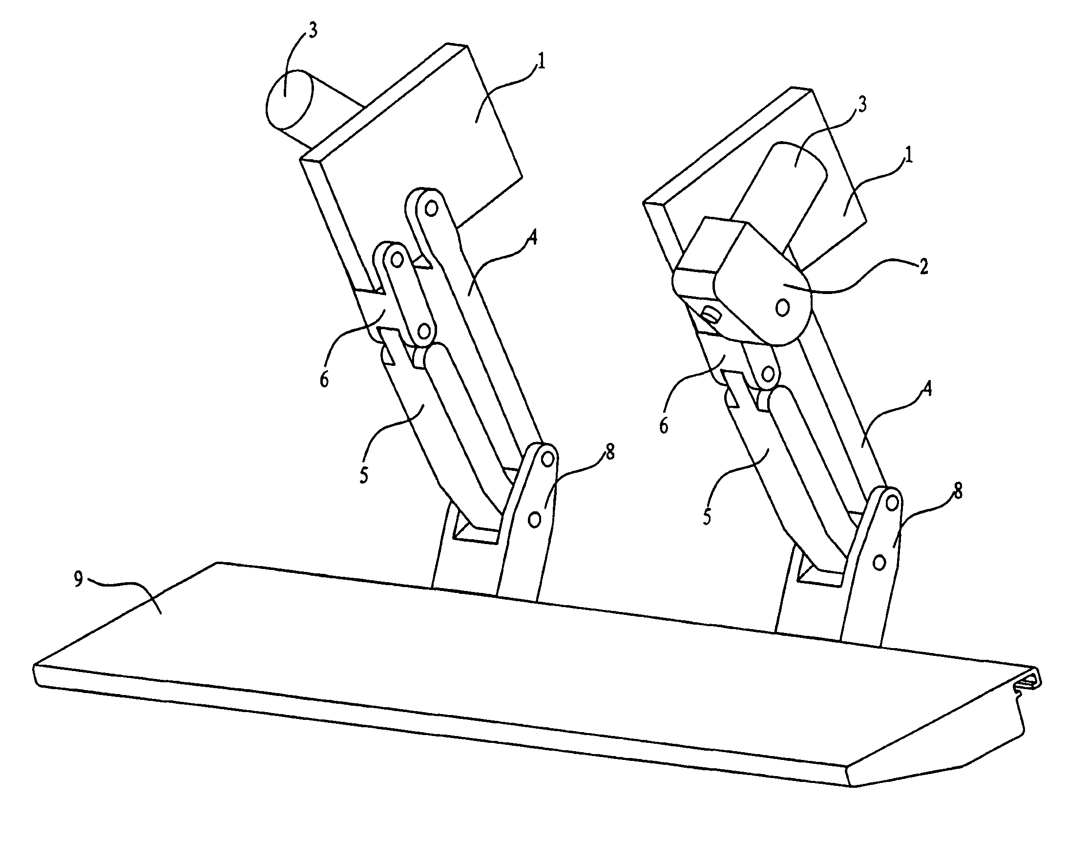
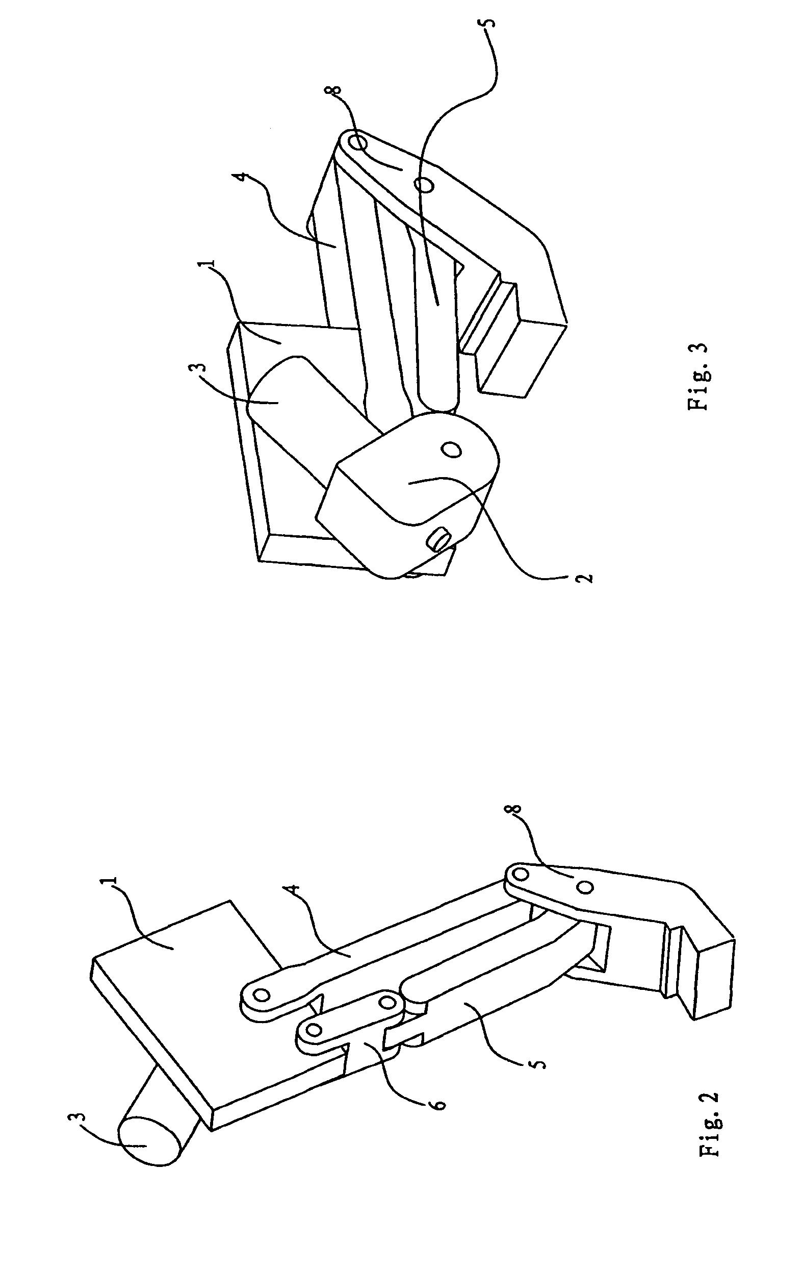
[0040]In operation of the extending and retracting device and as shown in FIGS. 2 and 3, when it is required to move the extending and retracting device from the extended state (as shown in FIG. 2) to the retracted state (as shown in FIG. 3), the reversible motor 3 rotates the first arm 4 in counter-clockwise direction (as viewed in FIG. 2) with respect to the mounting bracket 1 via the speed reducer 2, thus driving the second arm 5 and third arm 6 to rotate with respect to the mounting bracket 1 so that the step bracket 8 moves upwardly and rearwardly with respect to the mounting bracket 1. In this way, the extending and retracting device moves to its retracted state (as shown in FIG. 3). Through reversed rotation of the motor 3, the extending and retracting device can move from the retracted state (as shown in FIG. 3) to the extended state (as shown in FIG. 2).

[0041]It should be appreciated by those having ordinary skill in the related art that in the first embodiment of the exten...

third embodiment

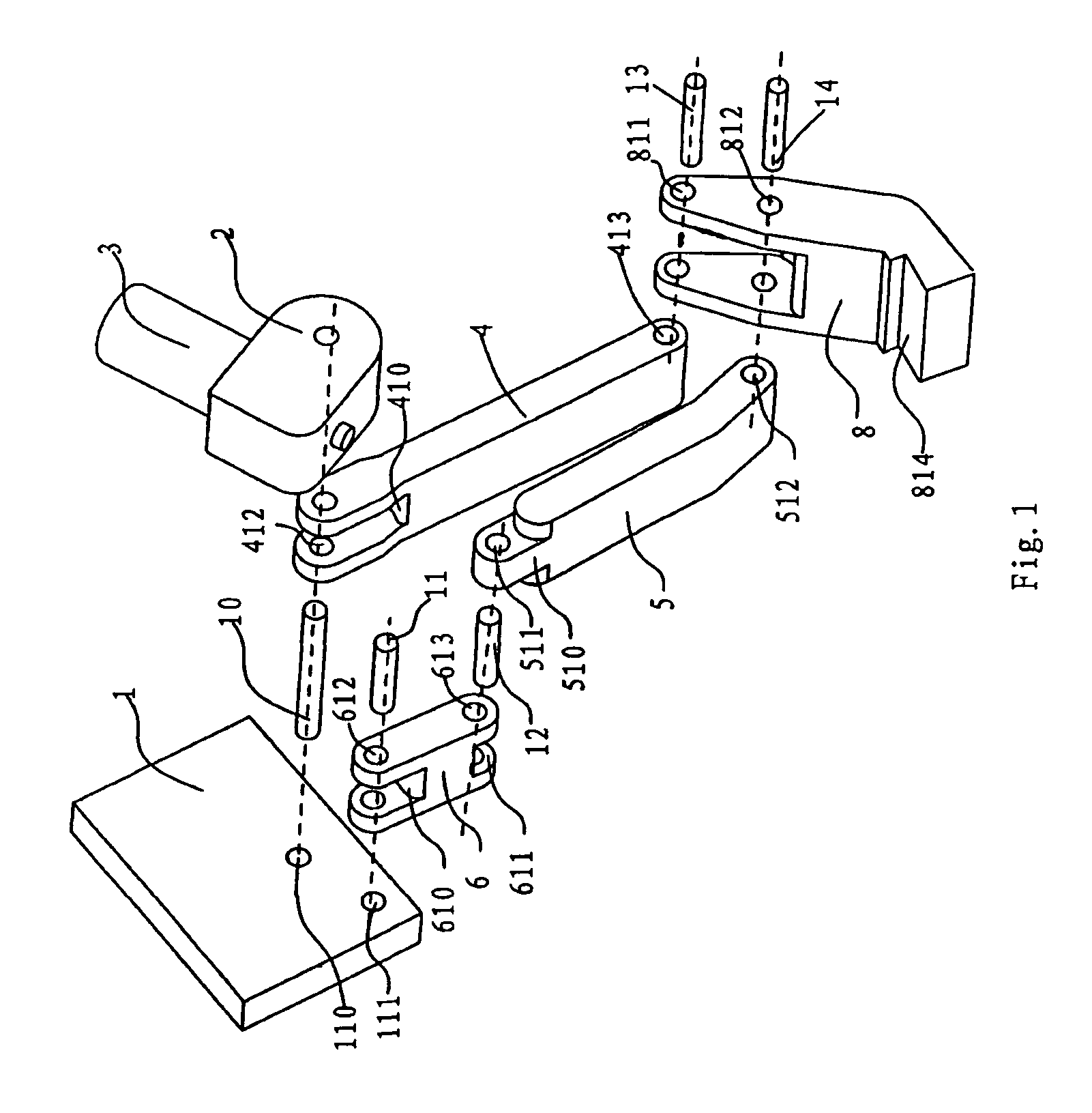
[0045]In the third embodiment, the respective lower end portions of the first arm 4 and second arm 5 are juxtaposed with respect to each other and connected to the step bracket 8. In other words, the respective lower end portions of the first arm 4 and second arm 5 are connected to the step bracket 8 side by side with respect to each other. A notch 414 is formed in the lower end portion of the first arm 4 such that the lower end portion of the first arm 4 is formed as a width-reduced protrusion portion, a notch 514 is formed in the lower end portion of the second arm 5 such that the lower end portion of the second arm 5 is formed as a width-reduced protrusion portion, and a notch 813 is formed in an upper portion of the step bracket 8 such that the upper portion of the step bracket 8 is formed as a width-reduced protrusion portion. In this way, the respective lower end portions of the first arm 4 and second arm 5 are connected via corresponding pins 13, 14 to the step bracket 8 side...

second embodiment

[0046]However, those having ordinary skill in the related art should appreciate that the respective lower end portions of the first arm 4 and second arm 5 and the upper portion of the step bracket 8 can be formed with no notches. Alternatively, the respective lower end portions of the first arm 4 and second arm 5 may be juxtaposed to the upper portion of the step bracket 8 directly. The term “juxtaposed” as used herein means that the step bracket 8 is not inserted into the first arm 4 and second arm 5 (as compared to the step bracket 8 of the second embodiment). Namely, the respective lower end portions of the first arm 4 and second arm 5 are connected to the step bracket 8 side by side with respect to each other.

[0047]With reference to FIG. 6, a fourth embodiment of the extending and retracting device for a vehicle step apparatus of the present invention will now be described. Those having ordinary skill in the related art should appreciate that structure and operation of the fourt...


PUM


Abstract

A vehicle step includes a step member and first and second extending and retracting devices connected to the step member for moving it between extended and retracted positions. Each of the extending and retracting devices includes a mounting bracket adapted to be fixed to a vehicle body, a step bracket connected to the step member, first and second arms each defining a lower end rotatably connected to the step bracket and an upper end, and a third arm defining an upper end rotatably connected to the mounting bracket and a lower end rotatably connected to the upper end of the first or second arm. The upper end of the other of the first or second arm is rotatably connected to the mounting bracket. The vehicle step includes also driving devices that drive respectively the extending and retracting devices to move the step member between the extended and retracted positions.

Description

BACKGROUND OF THE INVENTION[0001]1. Field of the Invention[0002]The present invention relates, generally, to a vehicle body and, more particularly, to a step of the vehicle body and an extending and retracting device for the step.[0003]2. Description of the Related Art[0004]A step under a door of a vehicle is used for a passenger to get on or off the vehicle. In terms of ergonomics, the vehicle step is generally mounted at a level of 15 cm with respect to the ground so that it is convenient for the passenger to get on or off it, but this level does not provide sufficient ground clearance during operation of many vehicles. The level of the vehicle step should be higher than ground clearance of the vehicle. Therefore, it is difficult to meet ground-clearance and convenience requirements simultaneously with a conventional vehicle step.[0005]U.S. Pat. No. 6,830,257 discloses a retractable vehicle step employing a four-link mechanism. When a door of a vehicle is opened, the vehicle step ...

Claims


Application Information

Patent Timeline
Patent Type & Authority Patents(United States)
IPC IPC(8): B60R3/00B60R3/02
CPCB60R3/02
Inventor YANG, HUIZHONGYANG, LINGLING
Owner HANGZHOU TIANMING TECH CO LTD
Why Eureka
Try Eureka