Rotation control device and working machine therewith

A technology for rotating control devices and operating machinery, applied in control systems, motor controls, electric controllers, etc., can solve the problems of not being able to control smoothly, not reflecting the working state, and discontinuous changes in torque, so as to suppress the occurrence of shocks Effect

Inactive Publication Date: 2008-08-27
KOBELCO CONSTR MASCH CO LTD
View PDF7 Cites 28 Cited by
  • Summary
  • Abstract
  • Description
  • Claims
  • Application Information

AI Technical Summary

Problems solved by technology

[0014] However, as in the above document, when switching between the two control systems, the switching point of the control system is to fill the gap between the control systems, the torque fluctuates discontinuously (suddenly), and it cannot be performed smoothly. stable control
[0015] In addition, in the technology of Patent Document 2, when the lever operation amount exceeds the central range, the larger torque of the on-site holding torque and the acceleration torque is used for rotational driving, but the on-site holding torque is passed through the center The torque required before the position holding control performed within the range does not reflect the current working state. Therefore, in terms of the torque to keep the rotating body on site, torque control is more effective than position holding. Under heavy working conditions during control, the rotating body may go against the operator's intention and go backwards

Method used


Image

  • Rotation control device and working machine therewith
  • Rotation control device and working machine therewith
  • Rotation control device and working machine therewith

Examples


Embodiment Construction

[0049] Hereinafter, preferred embodiments of the present invention will be described with reference to the drawings.

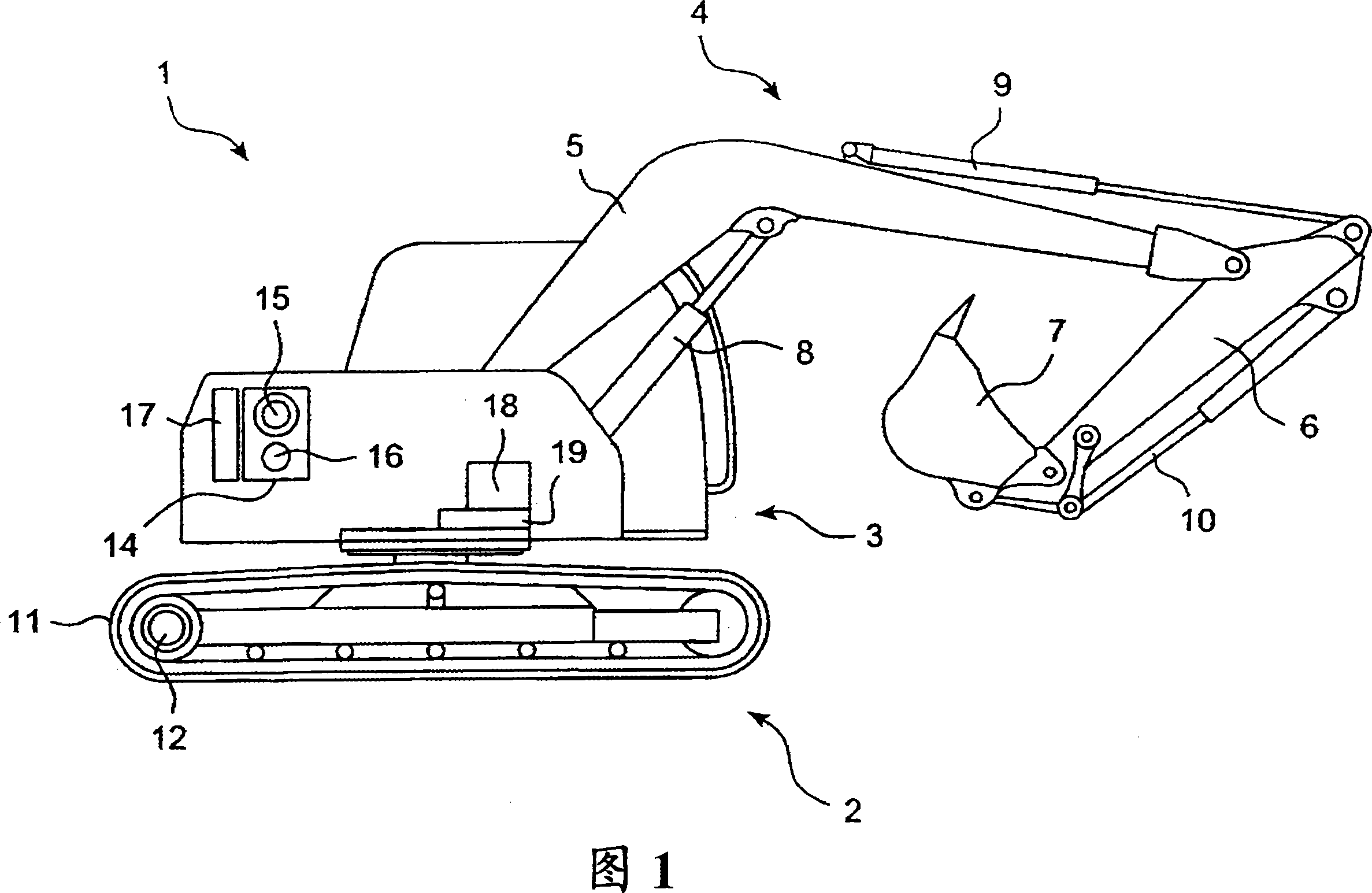
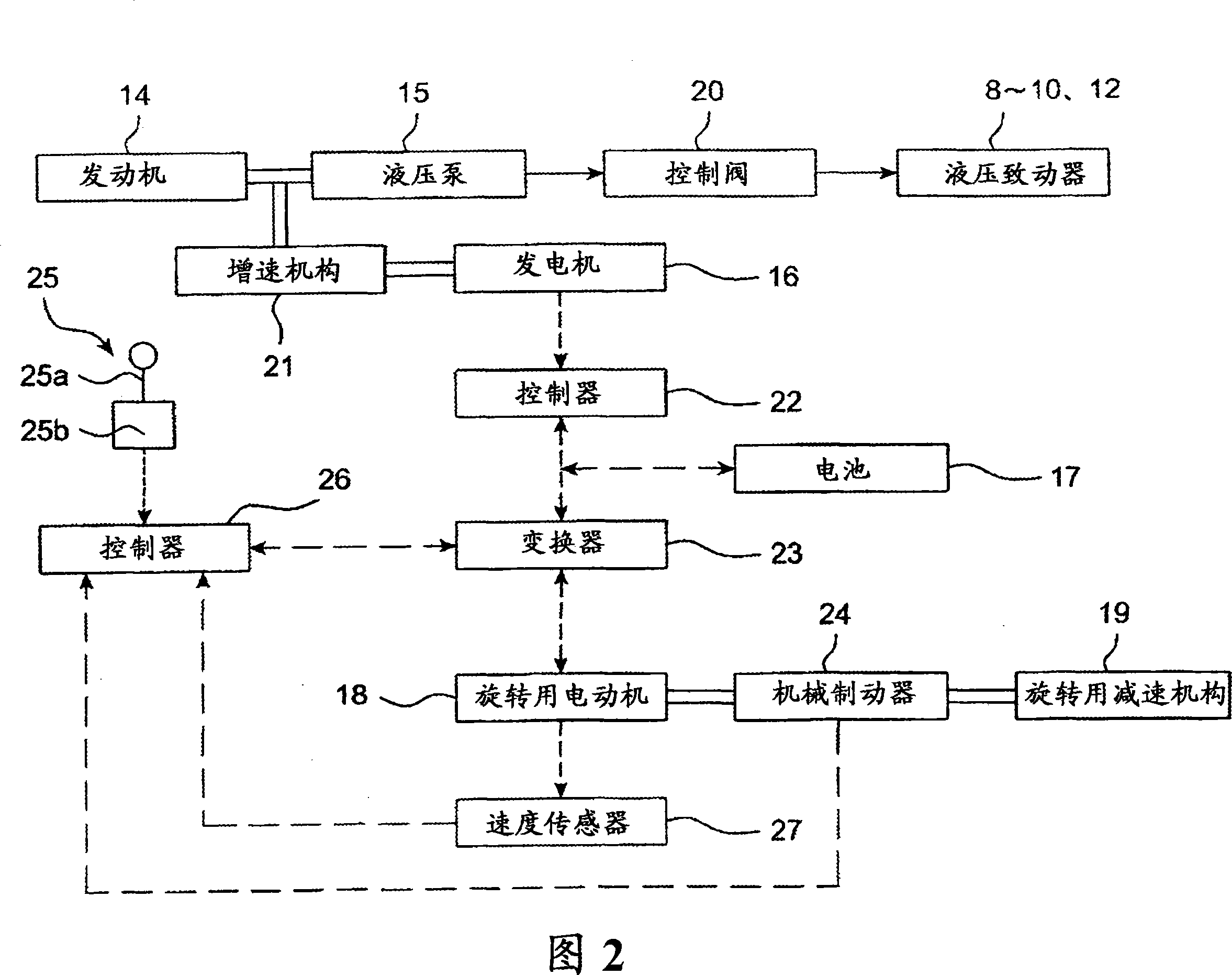
[0050] Fig. 1 shows a side view showing the overall structure of an excavator according to an embodiment of the present invention. Fig. 2 is a block diagram showing the structure of the drive and control system of the shovel of Fig. 1.

[0051] 1 and 2, an excavator 1 as an example of a working machine is provided with a crawler-type lower moving body 2 (main body), and an upper rotating body 3 rotatably mounted on the lower moving body 2 (main body) And a work attachment 4 mounted on the front part of the upper rotating body 3.

[0052] The work attachment 4 is provided with a boom 5 mounted on the upper rotating body 3 so as to be raised and lowered, a rocker arm 6 connected to the front end of the boom 5, a bucket 7 connected to the front end of the rocker arm 6, and The upper rotating body 3 drives the boom cylinder 8 of the boom 5, the rocker arm cylinder 9 t...


PUM


Abstract

A rotation control device and a working machine therewith are provided, comprising a controller capable of setting target torque of a rotation motor in accordance with a speed deviation between target speed set in accordance with an operation amount of an operating lever and actual rotation speed, and an inverter for detecting necessary torque for rotating an upper rotating body, the necessary torque being changed in accordance with a working state of the upper rotating body. The controller calculates a correction amount which is increased as increasing the torque and subtracts the correction amount from the target speed so as to set new target speed. A controller sets first target torque for driving the motor and second target torque for maintaining the upper rotating body on the spot on the basis of the actual speed, and operates the motor in accordance with the torque which has a larger absolute value in the same direction as the first target torque among both the torque.

Description

Technical field [0001] The present invention relates to a rotation control device for a working machine that drives a rotating body to rotate by a motor. Background technique [0002] Rotating work machines such as excavators and cranes use hydraulic motors driven by the discharge oil of a hydraulic pump as the driving source of the rotating body. However, in recent years, technologies using electric motors as the driving source have been known (e.g., JP 2001-10783 Publication No., hereinafter referred to as Patent Document 1). [0003] In this case, the speed control (the so-called speed feedback control) that determines the torque command by the deviation between the target speed set by the operation amount of the rotary operating lever and the actual rotation speed is executed. Therefore, once the deviation becomes larger, The acceleration torque will increase sharply, resulting in shock. [0004] Known techniques for coping with this phenomenon include: as in Japanese Patent ...

Claims


Application Information

Patent Timeline
Patent Type & Authority Applications(China)
IPC IPC(8): E02F9/20B66C23/84G05B11/32H02P29/00
CPCE02F9/123E02F9/128E02F9/207E02F9/2025
Inventor 鹿儿岛昌之筒井昭小见山昌之
Owner KOBELCO CONSTR MASCH CO LTD
Why Eureka
Try Eureka