Tensioner

A technology for tensioning devices and shaft components, applied in the direction of transmission devices, belts/chains/gears, mechanical equipment, etc., can solve problems such as easy fixation, and achieve the effect of ensuring normal operation

Active Publication Date: 2015-07-15
NHK SPRING CO LTD
View PDF6 Cites 0 Cited by
  • Summary
  • Abstract
  • Description
  • Claims
  • Application Information

AI Technical Summary

Problems solved by technology

[0034] In view of this, in the existing tensioning device, such as Figure 7-9 As shown, the contact radius R1 of the contact portion between the rear end 132 of the propulsion member and the stepped portion 122 of the rotating member is greater than the contact radius R2 of the screw thread (R1>R2), and R1 / R2>1>(-tan(θ2-α)) / μ1, so formula (108) is not satisfied, thereby forming a structure in which the abutting portion is easily fixed

Method used


Image

  • Tensioner
  • Tensioner
  • Tensioner

Examples


Embodiment approach 1

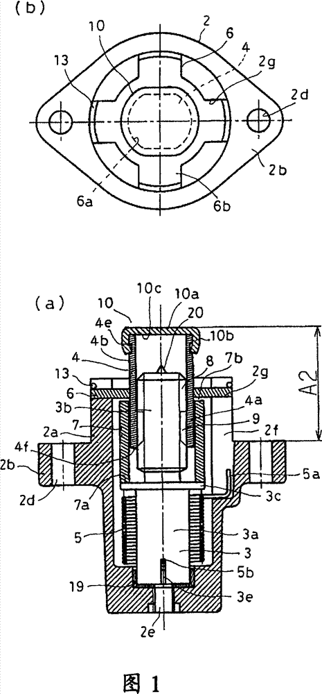
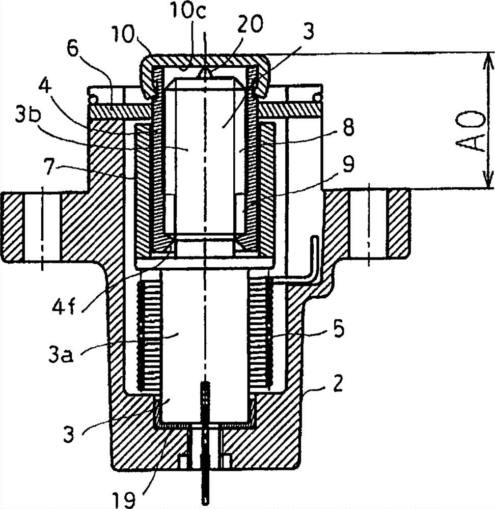
[0063] figure 1 is a longitudinal sectional view showing the tensioner according to Embodiment 1 of the present invention, figure 2 It is a longitudinal sectional view of the tensioning device in the fully retracted state. The tensioner of this embodiment roughly includes a housing 2, a first shaft member 3 as a rotating member, a second shaft member 4 as an advancing member, a torsion spring (elastic member) 5, a bearing 6, a spacer 7, these parts and Figure 7 The existing tensioner shown is substantially the same.

[0064] The housing 2 is shaped substantially in a bottomed cylindrical shape having a flange portion 2b in the middle of the cavity 2a. Furthermore, a storage hole 2c extending to the front end portion in the axial direction (propelling direction) is formed inside the cavity 2a. The front end portion of the housing hole 2c is open, and an assembly of the first shaft member 3, the second shaft member 4, the torsion spring 5, and the spacer 7 is housed in th...

Embodiment approach 2

[0086] image 3 It is a longitudinal sectional view showing the tensioner according to Embodiment 2 of the present invention.

[0087] In this embodiment, the front pointed contact portion 20 is removed from the front end surface of the first shaft member 3 in Embodiment 1, and the front pointed contact portion 20' is provided on the front end member 10' side, so The configuration is the same as that of Embodiment 1 except that the shape of the tip member 10' is different.

[0088] The front end part 10' is composed of a head part 10a' and a foot part 10b', and the head part 10a' covers the front end part of the cylindrical part 4b of the second shaft part 4, and the leg part 10b' is inserted into the front end part of the cylindrical part 4b. In the state where the spring pin (pin) 11 is pressed in, the separation of the leg portion 10b' from the cylindrical portion 4b is prevented, so that the front end member 10' is fixed to the cylindrical portion 4b. A contact portion 2...

Embodiment approach 3

[0093] Figure 4 It is a longitudinal sectional view showing the tensioner according to Embodiment 3 of the present invention. In this embodiment, the front pointed contact portion 20 ′ of the front end member 10 ′ in Embodiment 2 is removed, and is provided between the rear end 4 f of the second shaft member 4 and the stepped portion 3 c of the first shaft member 3 . Therefore, other configurations of the bearing member 30 such as a thrust bearing are basically the same as those of the second embodiment.

[0094] Therefore, when the second shaft member 4 retracts to the fully retracted state (A0 position), the rear end 4f of the second shaft member 4 is in a state of abutting against the bearing member 30 . At this time, the inner side of the leg portion 10b' of the front end member 10' is not in contact with the front end surface of the first shaft member 3 with only a slight gap, and the second shaft member 4 cannot retreat further from the protrusion dimension A0.

[009...


PUM


Abstract

A tensioner in which sticking between a rotation member and a drive member when the tensioner is in a fully retracted state is prevented by using a simple mechanism, thereby ensuring reduced man-hour for control in assembling the tensioner and enabling the tensioner to function when it is abnormally operated. A pair of shaft members (3, 4) is threaded to each other by thread sections (8, 9), and one (3) of the shaft members (3, 4) is rotatingly urged by a spring (5) and driven by rotational force transmitted from the one shaft member (3) with the other shaft member (4) restrained from rotating. A contact section (20) is formed at that portion of the shaft members (3,4) which is other than that of the thread sections (8, 9), and the contact section (20) come into contact with the other shaft member (4) when it is moved in the direction opposite the drive direction. The contact section (20) is set to satisfy the expression of R1 / R2 < -tan(µ2 - a) / µ1, where R1 is a contact radius caused by contact, R2 the effective diameter of the thread sections (8, 9), µ1 the coefficient of friction of the contact section (20), µ2 the coefficient of friction of the thread sections (8, 9), and a the lead angle of the thread faces of the thread sections (8,9).

Description

technical field [0001] The invention relates to a tensioning device which can adjust the tension of an endless belt or chain to keep the tension constant. Background technique [0002] The tensioner pushes the timing chain or belt used in the engine of a car such as a two-wheeled vehicle with a specified force and keeps its tension constant when it stretches or relaxes. [0003] Figure 6 It is a layout view showing a state in which the tensioner 100 is installed in the automobile engine body 200 . A pair of cam sprockets 210 , 210 and a crank sprocket 220 are arranged inside the engine main body 200 , and a timing chain 230 spans between these sprockets 210 , 210 , 220 in an endless shape. In addition, a swingable chain guide rail 240 is disposed on a moving path of the timing chain 230 , and the timing chain 230 can slide on the chain guide rail 240 . A mounting surface 250 is formed on the engine body 200 , and bolts 270 fix the tensioning device 100 on the mounting sur...

Claims


Application Information

Patent Timeline
Patent Type & Authority Patents(China)
IPC IPC(8): F16H7/08
CPCF16H7/0848F16H2007/0857F16H2007/081F16H2007/0806
Inventor 小林贵雄天野种平
Owner NHK SPRING CO LTD
Why Eureka
Try Eureka