
Tamp pad

A technology of padding and transfer printing, used in printing, printing presses, rotary printing presses, etc.

Inactive Publication Date: 2005-11-16
TELEFON AB LM ERICSSON (PUBL)
View PDF0 Cites 0 Cited by
  • Summary
  • Abstract
  • Description
  • Claims
  • Application Information

AI Technical Summary

Problems solved by technology

This is a big problem because this method will be limited to use on workpieces that do not have the complex shapes described above

Method used


Image

  • Tamp pad
  • Tamp pad
  • Tamp pad

Examples


Embodiment Construction

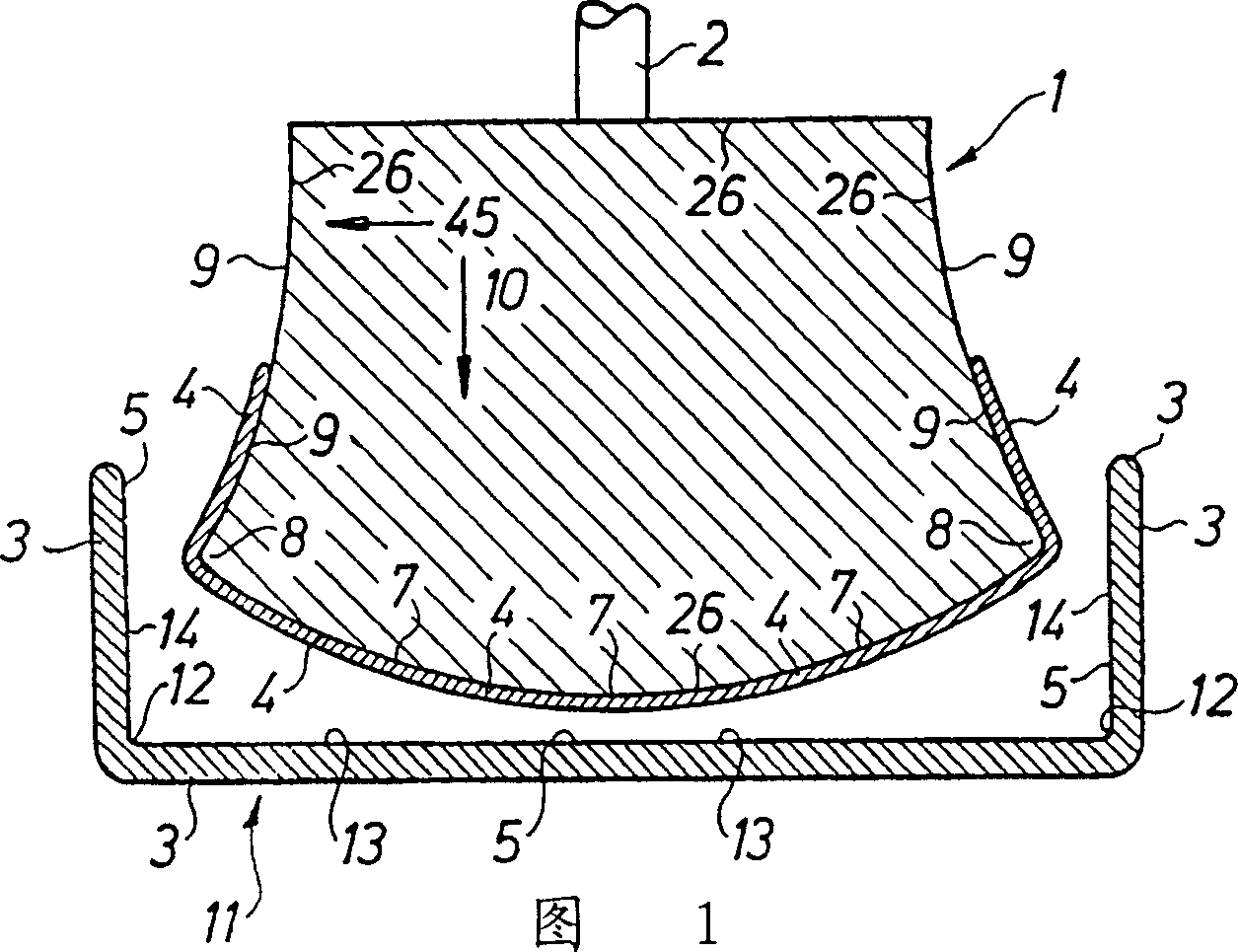
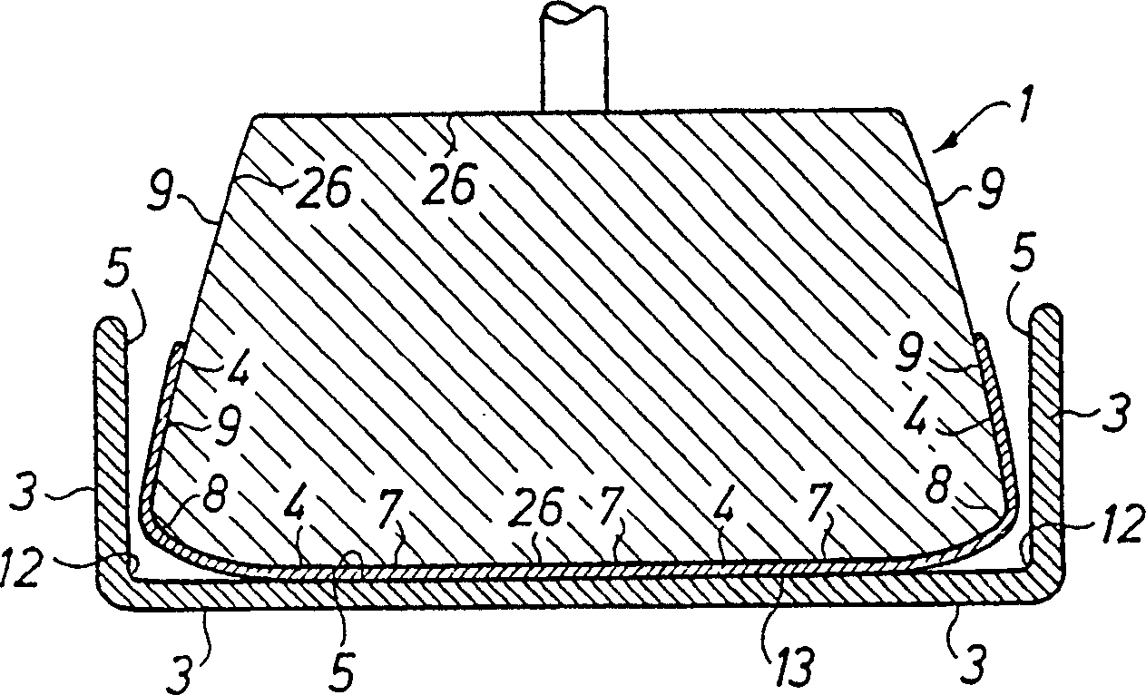
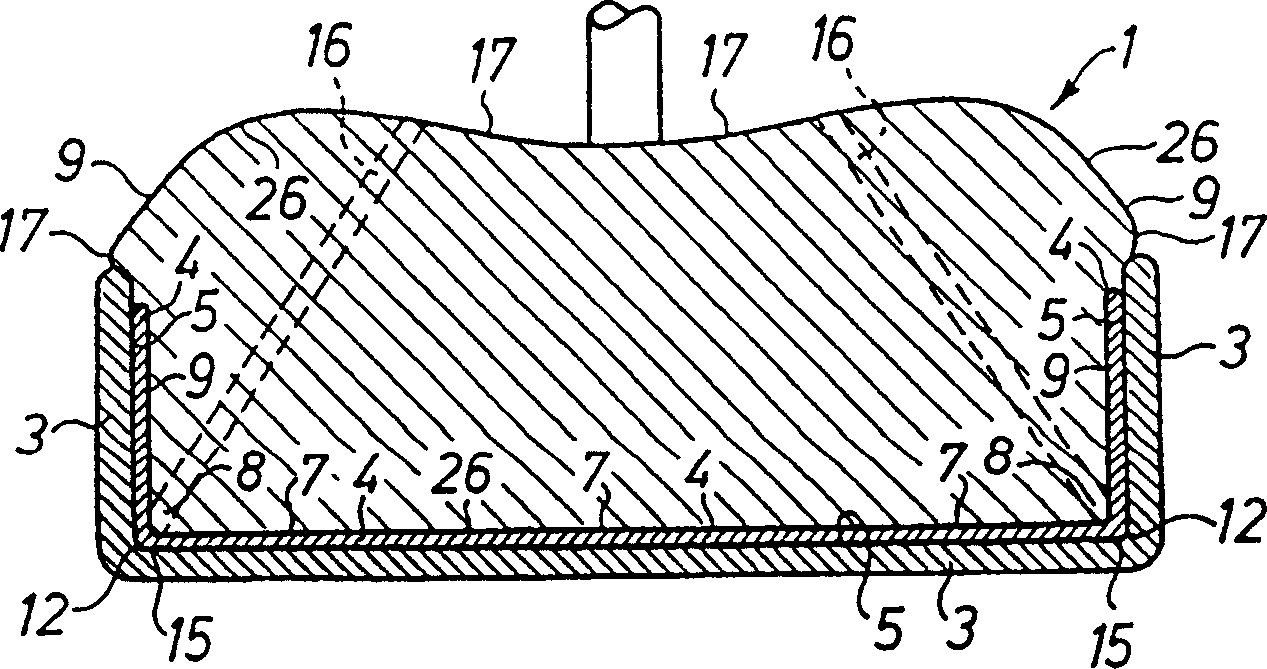
[0021] The first stage in the padding printing method is shown in Fig. 1, the apparatus of the present invention has a padding pad 1 of a first embodiment, this pad is made by a kind of soft material (preferably silicon), and it is substantially along the Move in direction 10. The pad is fixed on a fixture 2 of the pad printing machine, and an image 4 preferably consisting of a color containing metal fragments for conducting electricity can be removed from a printing plate and then printed on the workpiece 3 on, for example on the inner side 5 of the mobile phone cover 11 . The packing pad 1 has several outer boundary surfaces 26 , of which at least one side 7 has a convex shape, and several boundary surfaces adjoining it, which form several corners 8 and at least two concave surfaces 9 . The workpiece 3 has on its inner side 5 several corners 12 , a base 13 and at least two side faces 14 .

[0022] figure 2 The second stage of the pad printing method is shown in . A porti...


PUM


Abstract

Tamp printing of at least one picture (4) occurs by means of at least one tamp pad (1, 18, 24, 34) on a piece (3), which has boundary surfaces (5, 13) forming angles relative to each other, the tamp pad first printing in one direction (10) against a boundary surface (13, 43) and thereafter, after further compression of the tamp pad (1) against said boundary surface (13) due to its deformation, prints in another direction (45) than the direction (10) against another boundary surface or other boundary surfaces (5, 43), whereby the picture is transferred to said boundary surfaces.

Description

technical field [0001] The present invention relates to a pad device and pad printing method for simplifying the printing process, wherein ink is applied to a pad which prints an image onto a workpiece having concave surfaces and a convex bottom surface, The pad has a conformal shape to the workpiece for printing on the bottom and sides of the workpiece, and the pad is provided with several channel means for evacuating the air accumulated between the workpiece and the pad so that the ink can be applied on hard-to-reach surfaces. Background technique [0002] In such devices appearing on the market, it is possible to transfer an image onto those slightly curved surfaces of a workpiece, such as a sphere, the front of a mobile phone, etc., by a method called pad printing. The principle of tamp printing with metallic inks has been described, for example, in patent documents PCT / SE97 / 00372 and PCT / SE98 / 01678, the contents of which are incorporated herein by reference. With exis...

Claims


Application Information

Patent Timeline
Patent Type & Authority Patents(China)
IPC IPC(8): B41F17/00B41M1/40H05K9/00
CPCH05K9/0045B41M1/40B41F17/006H05K9/0022
Inventor P·霍姆贝里L·艾利松
Owner TELEFON AB LM ERICSSON (PUBL)
Learn More