Auto-loading firearm with gas piston facility

Active Publication Date: 2010-11-16
BARRETT FIREARMS MFG INC
View PDF10 Cites 89 Cited by
  • Summary
  • Abstract
  • Description
  • Claims
  • Application Information

AI Technical Summary

Benefits of technology

[0007]The present invention overcomes the limitations of the prior art by providing a firearm having a body with a bolt assembly reciprocating within the body. A barrel having a bore extends from the body. A gas block with an elongated chamber is connected to the barrel, and a gas passage connects the barrel bore to the gas block chamber. An operating rod has a forward end portion closely received in the gas block chamber and a rear end positioned to

Problems solved by technology

In a gas-operated system, this gas is exhausted into the action, so that the bolt assembly and trigger mechanism may become fouled, and so that the chamber into which cartridges are loaded becomes coated with the contaminants.
This reduces dimensions, and increases friction, leading to stoppages caused by failures to chamber a round, and failures to extract spent casings.
In piston-operated systems, the action remains free of gas fouling, but the piston itself becomes fouled.
The piston requires a close fit in the g

Method used


Image

  • Auto-loading firearm with gas piston facility
  • Auto-loading firearm with gas piston facility
  • Auto-loading firearm with gas piston facility

Examples


Embodiment Construction

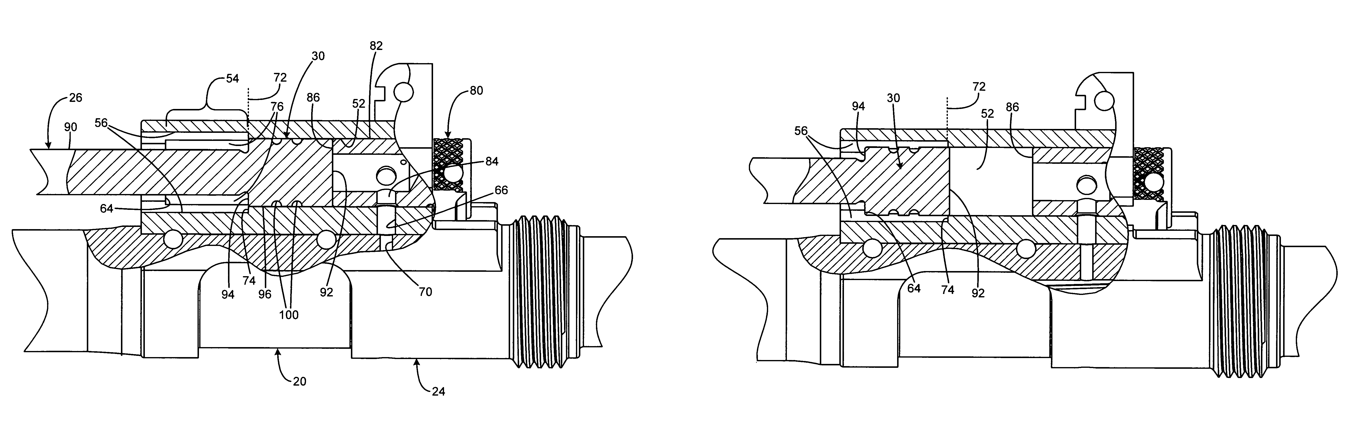
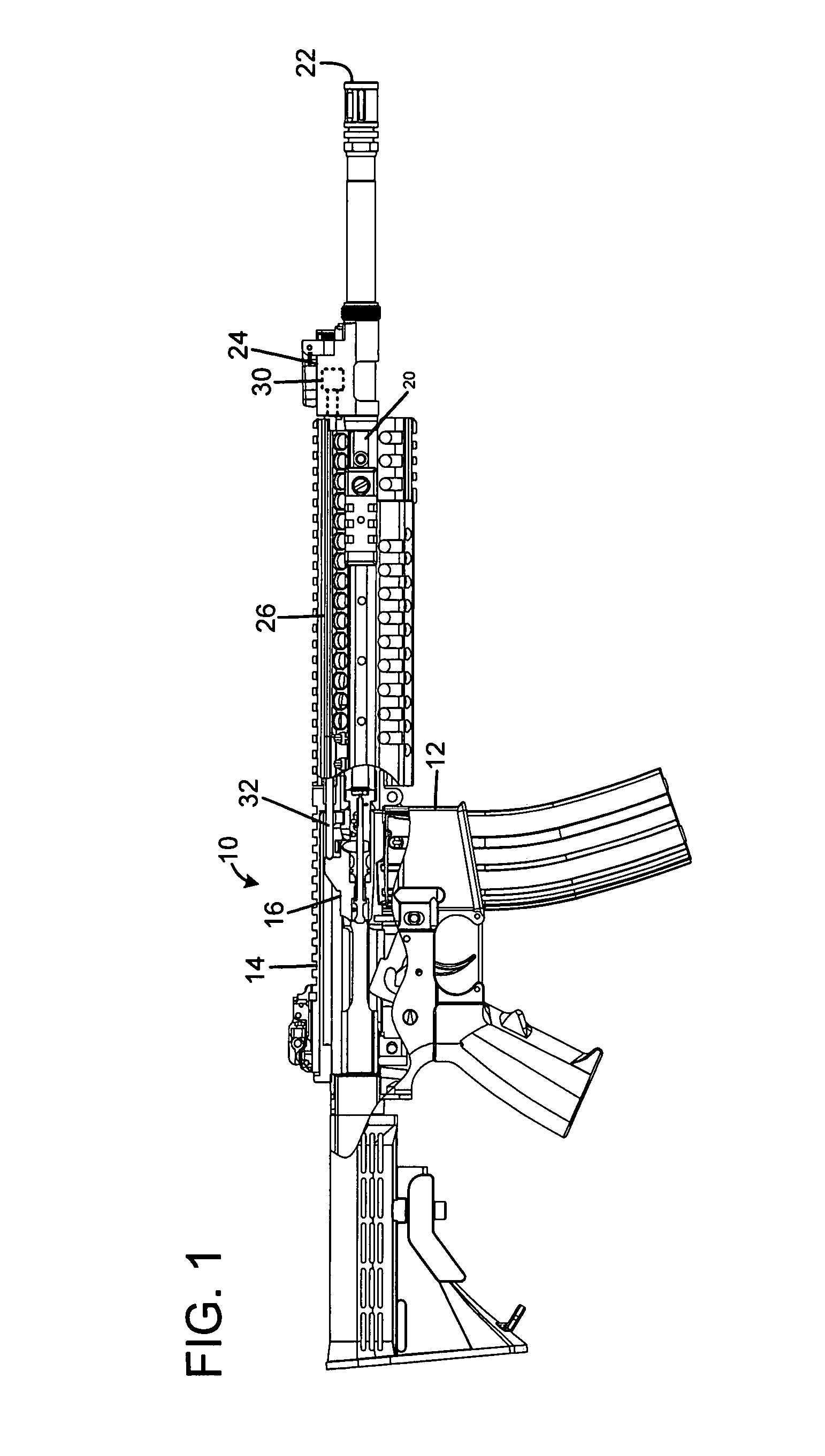
[0013]FIG. 1 shows a rifle 10 having a lower receiver 12, and an upper receiver 14 in which a bolt assembly 16 reciprocates. A barrel 20 extends forward from the upper receiver to a muzzle end 22. A gas block 24 is mounted to the barrel at an intermediate position near the muzzle. An operating rod 26 has a cylindrical piston 30 at a forward end, and has a rear end 32 that extends into the upper receiver 14, and which is registered with a portion of the bolt assembly 16. As will be discussed below, the piston 30 is closely received within a cylindrical bore in the gas block, and a passage extends between the cylinder and the barrel bore. Upon firing, some of the pressurized column of gas behind the bullet enters the gas block chamber and forces the piston rearward. The rod then transmits energy to the bolt assembly, cycling it rearward to load another round.

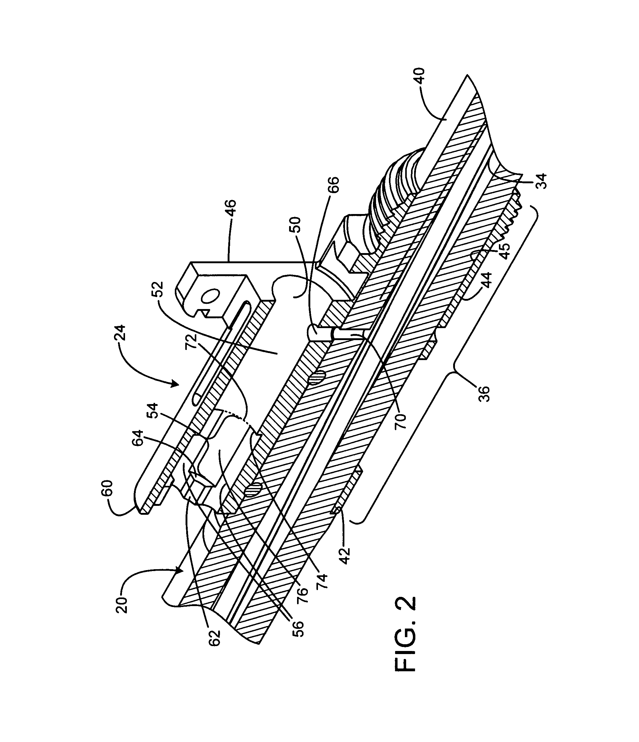
[0014]FIGS. 2 and 3 show the gas block 24 as mounted on the barrel 20. The barrel bore 34 extends axially through the barrel. Th...


PUM


Abstract

A firearm has a body with a bolt assembly reciprocating within the body. A barrel having a bore extends from the body. A gas block with an elongated chamber is connected to the barrel, and a gas passage connects the barrel bore to the gas block chamber. An operating rod has a forward end portion closely received in the gas block chamber and a rear end positioned to operably engage the bolt assembly. The gas block chamber has a forward portion closely receiving the forward end portion of the rod, and the gas block chamber has a rear portion with a profile larger than the forward portion. The forward portion of the rod may be a cylinder, and the rear portion of the gas block chamber may be fluted to provide clearance for flushing out contaminants. The rod may rotate freely to prevent accumulation of contaminants.

Description


Claims


Application Information

Patent Timeline
Owner BARRETT FIREARMS MFG INC
Why Eureka
Try Eureka