Combined oil control ring

Active Publication Date: 2018-04-26
RIKEN CO LTD
View PDF1 Cites 2 Cited by
  • Summary
  • Abstract
  • Description
  • Claims
  • Application Information

AI Technical Summary

Benefits of technology

[0023]The oil ring of the present invention has bottoms which are center-raised when viewed along a substantially circumferential direction and a radial direction, in intermediate portions of a spacer expander; the center-raised bottoms making it possible to surely flow oil out of the intermediate portions to their circumferential or radial sides. Particularly by a circumferential oil flow, oil can flow to large-space lower portions of the spacer expander, so that the retention of oil is surely

Problems solved by technology

In automobile engines, lubricating oil is exposed to a blowby gas and heated for a long period of operation, so that the lubricating oil is contaminated with unburned hydrocarbons and degenerated oil additives (called “oil sludge” as a whole).
The oil sludge attached to and accumulated on engine parts likely wears the parts and clogs lubricating oil paths, causing troubles in the functions of engine parts such as combined oil control rings (called “oil rings” unless otherwise mentioned).
In the oil rings, spacer expanders and side rails are stuck to each other in the worst case, hinderi

Method used


Image

  • Combined oil control ring
  • Combined oil control ring
  • Combined oil control ring

Examples


Example

Example 1

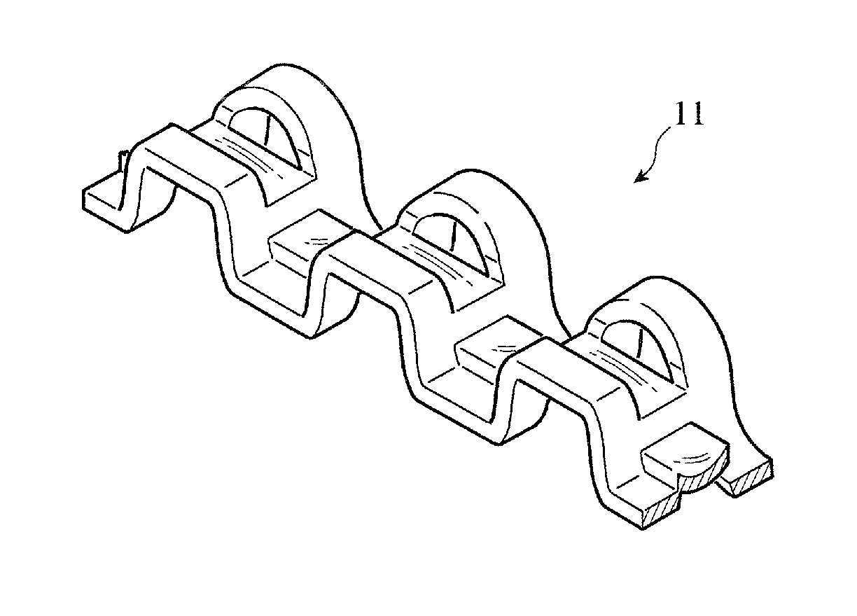
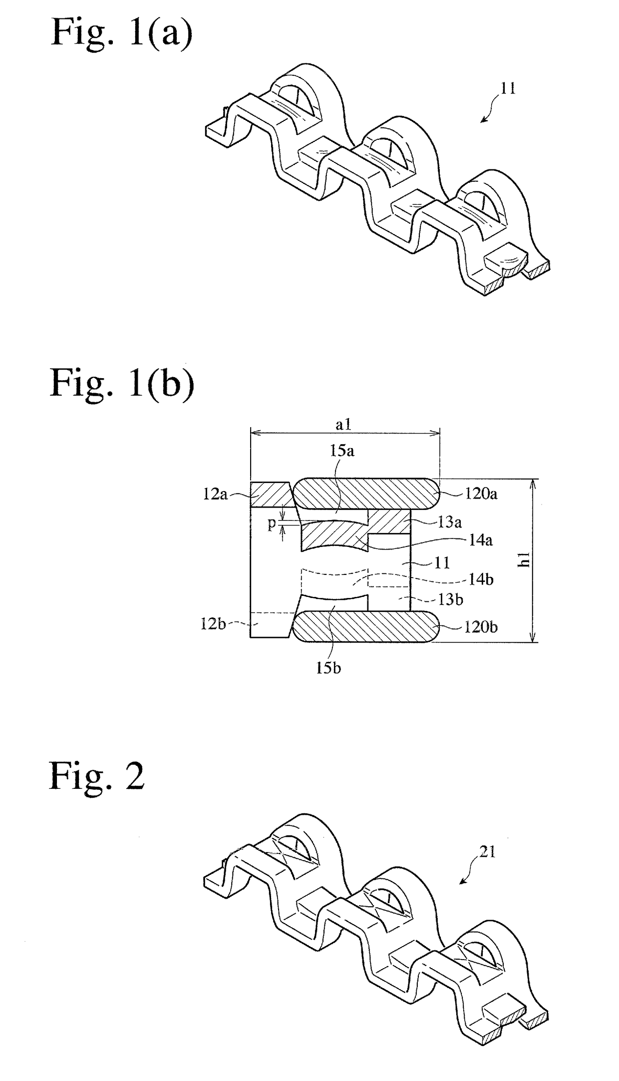
[0034]A SUS440 wire of 0.35 mm×1.72 mm was formed into side rails, and a SUS304 wire of 0.25 mm×1.9 mm was formed into a spacer expander, to produce a combined oil ring having a nominal diameter d1 of 71 mm, a combined nominal width h1 of 2.0 mm, and a combined thickness a1 of 2.3 mm. The spacer expander had a pitch of 2.7 mm from an upper portion (lower portion) to an upper portion (lower portion), and each center-raised bottom in the intermediate portion had a curved surface shape with a height p of 0.1 mm as shown in FIGS. 1(a) and 1(b). There were spaces 15a, 15b of 0.1 mm between the highest points of the center-raised bottoms and the side rails.

Example

Example 2

[0035]As shown in FIG. 2, a combined oil ring was produced in the same manner as in Example 1, except for changing each center-raised bottom in the intermediate portion of the spacer expander to a square-pyramid-shaped bottom. The height p of each center-raised bottom was 0.1 mm. Space 15a, 15b between the highest point of each center-raised bottom and each side rail was as wide as 0.1 mm.

Example

Comparative Example 1

[0036]As shown in FIGS. 3(a) and 3(b), a combined oil ring was produced in the same manner as in Example 1, except for using a conventional spacer expander having flat intermediate portions with no center-raised bottoms. The distance between a side-rail-supporting surface of each projection and each intermediate portion was 0.1 mm.


PUM


Abstract

To provide a combined oil control ring comprising a pair of upper and lower side rails and an axially corrugated spacer expander having upper and lower portions for automobile engines, which is capable of keeping an excellent oil-controlling function without sticking between a spacer expander and side rails even in a long period of engine operation, the upper and lower portions of the spacer expander have tabs pushing inner peripheral surfaces of the side rails, projections supporting the side rails, and intermediate portions between the tabs and the projections; and each intermediate portion opposing the side rail has a center-raised bottom having a center-raised shape when viewed along a substantially circumferential direction center-raised shape and a radial direction.

Description

FIELD OF THE INVENTION[0001]The present invention relates to a combined oil control ring mounted to pistons assembled in internal combustion engines, particularly to a combined oil control ring comprising a pair of upper and lower side rails and an axially corrugated spacer expander having upper and lower portions.BACKGROUND OF THE INVENTION[0002]In automobile engines, lubricating oil is exposed to a blowby gas and heated for a long period of operation, so that the lubricating oil is contaminated with unburned hydrocarbons and degenerated oil additives (called “oil sludge” as a whole). The oil sludge includes oil sludge precursors having relatively low viscosity. The oil sludge attached to and accumulated on engine parts likely wears the parts and clogs lubricating oil paths, causing troubles in the functions of engine parts such as combined oil control rings (called “oil rings” unless otherwise mentioned). In the oil rings, spacer expanders and side rails are stuck to each other in...

Claims


Application Information

Patent Timeline
IPC IPC(8): F16J9/06
CPCF16J9/068F02F5/00
Inventor SHIMIZU, HIROSHIICHIKAWA, TAKAYUKIMOCHIDUKI, KAZUYA
Owner RIKEN CO LTD
Why Eureka
Try Eureka