Cutting tube

A technology for cutting tubes and slits, applied in the fields of application, tobacco, and paper cigarette manufacturing, which can solve problems such as poor cutting quality, production interruption, and limited machine availability, and achieve the effect of preventing deposition

Active Publication Date: 2010-12-01
HAUNI MASCHINENBAU AG
View PDF11 Cites 2 Cited by
  • Summary
  • Abstract
  • Description
  • Claims
  • Application Information

AI Technical Summary

Problems solved by technology

[0005] Furthermore, it can happen that glue deposits on parts of the system involved in the cutting (such as knives or strip guides or cutting tubes), which can lead to poor cutting quality of the sections (Schnittqualitaet) or even production interruptions
In order to avoid this, manual cleaning processes have to be carried out again and again, which are only possible when the machine is at a standstill and thus limit the availability of the machine

Method used


Image

  • Cutting tube
  • Cutting tube
  • Cutting tube

Examples


Embodiment Construction

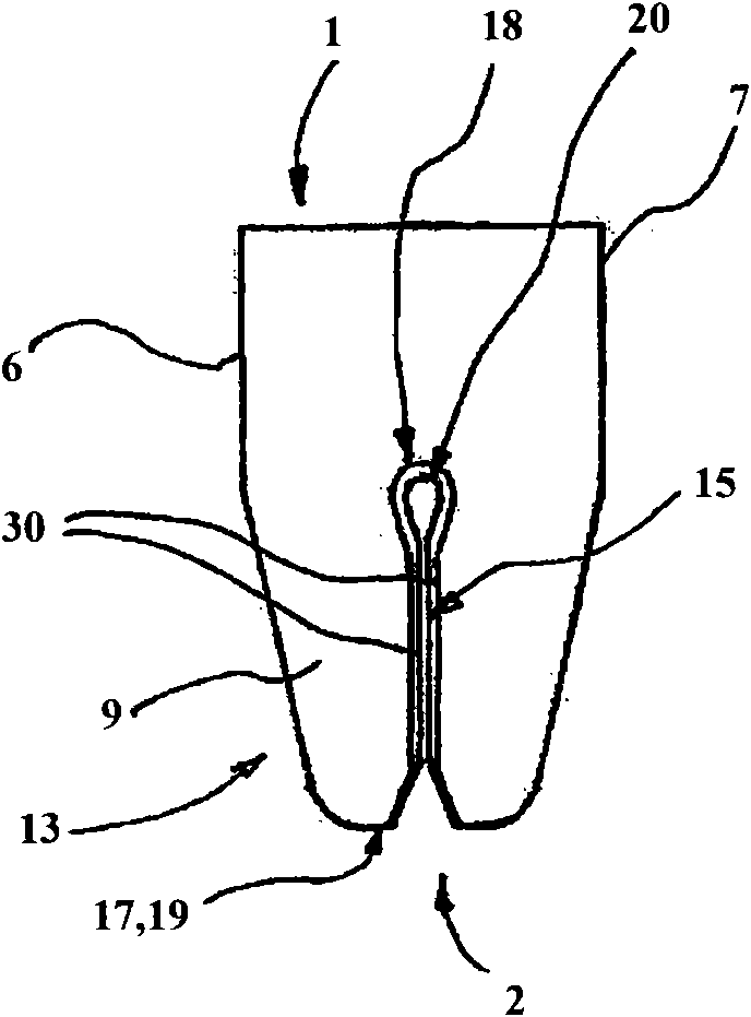
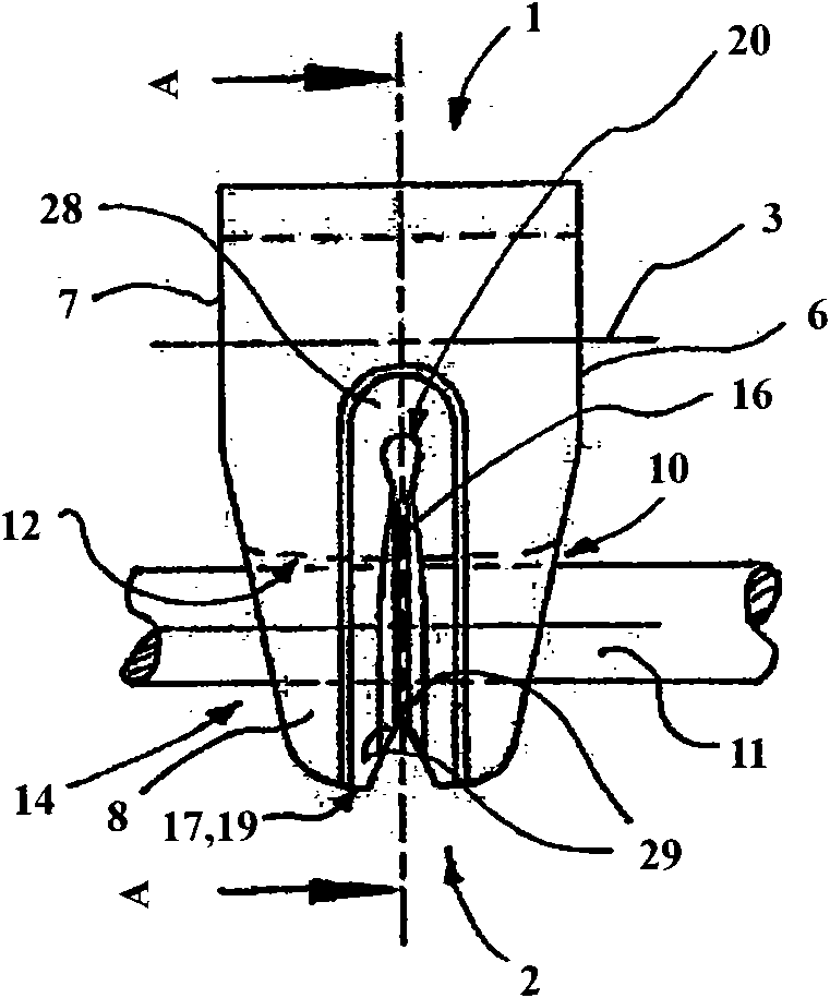
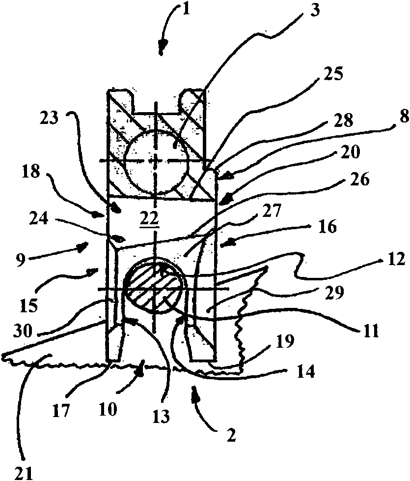
[0054] exist Figure 1 to Figure 4 The cutting tube shown in is substantially constructed almost like a double fork (Doppel-Gabel) and comprises two guiding forks arranged transversely relative to each other, one of which is located in the strip 11 guides the strip 11 during the cutting of the strip and the other guides the knife 21 during the cutting of the strip.

[0055] The cut tube comprises a fastening end 1 and a free end 2 opposite the fastening end 1, as shown in particular by image 3 as visible.

[0056] The fastening end 1 is provided with a rectangular fastening groove in cross-section that is open upwards and outwards for receiving a likewise not shown form of a support arm (not shown). The fastening end 1 is provided with a cylindrical bore 3 extending parallel to the aforementioned groove for receiving a not shown clamping bolt, which has two threaded holes for receiving a fastening screw. The bottom of the aforementioned fastening groove has two pass-through ...


PUM


Abstract

The invention relates to a cutting tube, concretely a cutting tube of a strip matter (11) for the tobacco industry. The tube has a an inlet side (8) and a discharge side (9) arranged opposite to the inlet side (8). A groove (10) with the strip matter (11) is opened for radial alternative overlaping and releasing of the strip matter (11) and provided with a first passage gap (15) and a second passage gap (16) and allows the operation without frequent maintenance and ensures the visul cutting quality by the following ways: namely the heat end (20) of the second passage gap (16) and/or the head end (18) of the first passage gap (15) comprises the passage cross-section extending towards the discharge side (9).

Description

technical field [0001] The invention relates to a cutting tube (Schneidtube) for a rod (Strang) in the tobacco processing industry, which has a fastening end and a free end (freienEnde) opposite to the fastening end; and has a first End side (Stirnseite), second end side opposite to the first end side, entry side (Eintrittsseite) arranged approximately transversely to the first end side and the second end side, exit side arranged opposite the entry side side (Austrittsseite); and with overlapping (uebergreifen) strips, slots open at one end of the cutting tube for radially alternating overlapping and releasing (Freigeben) of the strips for cutting During the guidance of the bar, the groove has a groove bottom extending from the first end side to the second end side and a first groove wall extending outward from the groove bottom (Nutgrund) and facing the first groove wall and a second groove wall extending outwards from the groove bottom, wherein the first groove wall is boun...

Claims


Application Information

Patent Timeline
Patent Type & Authority Applications(China)
IPC IPC(8): A24C5/28
CPCA24C5/28
Inventor M·卢恩伯格
Owner HAUNI MASCHINENBAU AG
Why Eureka
Try Eureka