Exhaust gas treatment catalyst

a technology of exhaust gas treatment and catalyst, which is applied in the direction of physical/chemical process catalysts, other chemical processes, separation processes, etc., can solve the problems of dampening out the normal air/fuel cycle used in engine controller strategies, and reducing the efficiency of the catalytic converter. , to achieve the effect of reducing the cost of catalyst, and improving the coating structur

Inactive Publication Date: 2005-10-13
BASF CATALYSTS LLC
View PDF33 Cites 77 Cited by
  • Summary
  • Abstract
  • Description
  • Claims
  • Application Information

AI Technical Summary

Benefits of technology

[0043] An additional advantage of the invention includes providing an improved coating architecture for certain commonly used monoliths. For monoliths containing channels with a rectangular or square shape, the first, i.e., bottom, layer effectively rounds off the corners thus creating a more effective coating surface for subsequent layers, such as the oxygen storage component layer and the catalytic layers containing platinum group metals as catalytic agents, that are coated on top of the bottom layer. The rounding-off of the corners is illustrated in FIG. 6 and is discussed in greater detail below. The second layer can be adhered directly on the bottom layer and a catalytic layer including a PGM catalytic agent, for example, can be adhered directly on the second layer. The rounded corners prevent the catalyst washcoat from deposition in the corners where it is less accessible for contacting the exhaust gas. Due to the increased accessibility of the catalytic layer to the exhaust gas, a thinner washcoat of the catalytic layer can be used in the catalyst without sacrificing TWC catalyst performance. The thinner catalytic layer is formed from washcoat compositions having lower solids content than catalyst washcoat compositions used in preparing conventional TWC catalysts. This feature significantly reduces platinum group metal use and cost without sacrificing TWC efficiency.
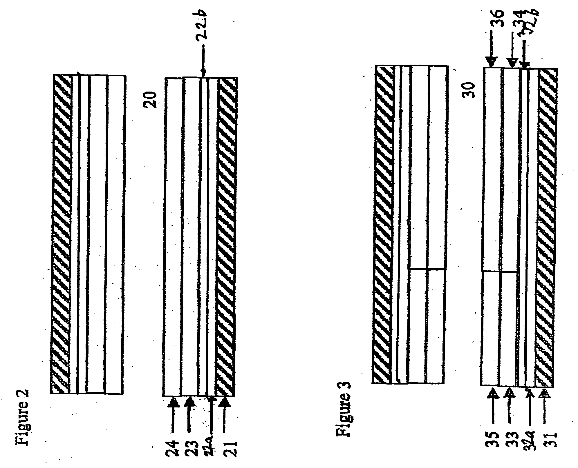
[0044]FIG. 2 depicts a layered composite of the invention having a single channel (20). A discrete coat of the bottom layer (22a) comprising substantially only a refractory metal oxide is coated as a “washcoat” onto carrier wall (21). Thereafter, a discrete coat of the second layer (22b) comprising substantially only at least one oxygen storage component and at least one binder therefor is coated as a washcoat onto the surface of layer (22a). Subsequently, a discrete coat of the third layer (23) comprising a catalytic material is coated as a washcoat onto the surface of second layer (22b) and a discrete coat of the fourth layer (24). The optional overcoat layer that may be coated as a discrete layer on the surface of layer (24) is not depicted in FIG. 2. The bottom layer (22a) would be coated on and adhered to the carrier wall (21). The second layer (22b) would be adhered to the bottom layer (22a). The third layer (23) overlying and adhering to the second layer (22b) and the fourth layer (24) overlying and adhering to the third layer (23) would be provided in one zone. With this arrangement, the gas being contacted with the catalyst, e.g., being flowed through the passageways of the catalytic material-coated carrier, will first contact the fourth layer (24), pass therethrough in order to contact the third layer (23), thereafter contacting the second layer (22b) and then lastly will contact the bottom layer (22a). The multi-layered composite depicted in FIG. 2 can be located in a close-coupled position or, alternatively, in an underbody position.
[0045] In an alternative configuration, the fourth layer need not overlie the third layer but can be provided in an upstream first zone (as sensed in the direction of gas flow through the catalyst composition) portion of the carrier, with the third layer provided on a downstream second zone portion with both zones supported on the second layer which in turn is supported on the bottom layer. In order to apply the washcoat in this configuration, an upstream first zone longitudinal segment only of the carrier (which had been previously coated with the bottom and the second layers) would be dipped into a slurry of the fourth layer of catalytic material, and dried, and the downstream second zone longitudinal segment of the carrier would then be dipped into a slurry of the third layer of catalytic material and dried.
[0046] Another preferred catalyst of the invention is a multi-zoned, multi-layered composite. As is shown in a channel (30) of this catalyst depicted in FIG. 3, this catalyst has a bottom refractory metal oxide layer (32a) overlying and adhering to the carrier wall (31), preferably of a honeycomb carrier, a second oxygen storage component+binder layer (32b) on top of and adhering to the bottom layer, a third catalytic layer on top of and overlying and adhering to the second layer and a fourth catalytic layer overlying and adhering to the third layer. Each third and fourth catalytic layer contains two zones, an upstream and a downstream zone. The second upstream zone (35) overlies and adheres to the first upstream zone (33), and the second downstream zone (36) overlies and adheres to the first downstream zone (34). Each of the first upstream, second upstream, first downstream, and second downstream zones are catalytic zones.
[0047] The first upstream zone contains a first upstream platinum component, a first upstream palladium component, and a first upstream refractory metal oxide support. The first downstream zone has a first downstream platinum component, a first downstream rhodium and a first downstream refractory metal oxide support. The second upstream zone includes a second upstream platinum component, a second upstream rhodium component, and a second upstream refractory metal oxide support. The second downstream zone has a second downstream platinum component, a second downstream palladium component and a second downstream refractory metal oxide support. The upstream and downstream zones can be reversed if hydrocarbon conversion has the higher priority than NOx conversion.
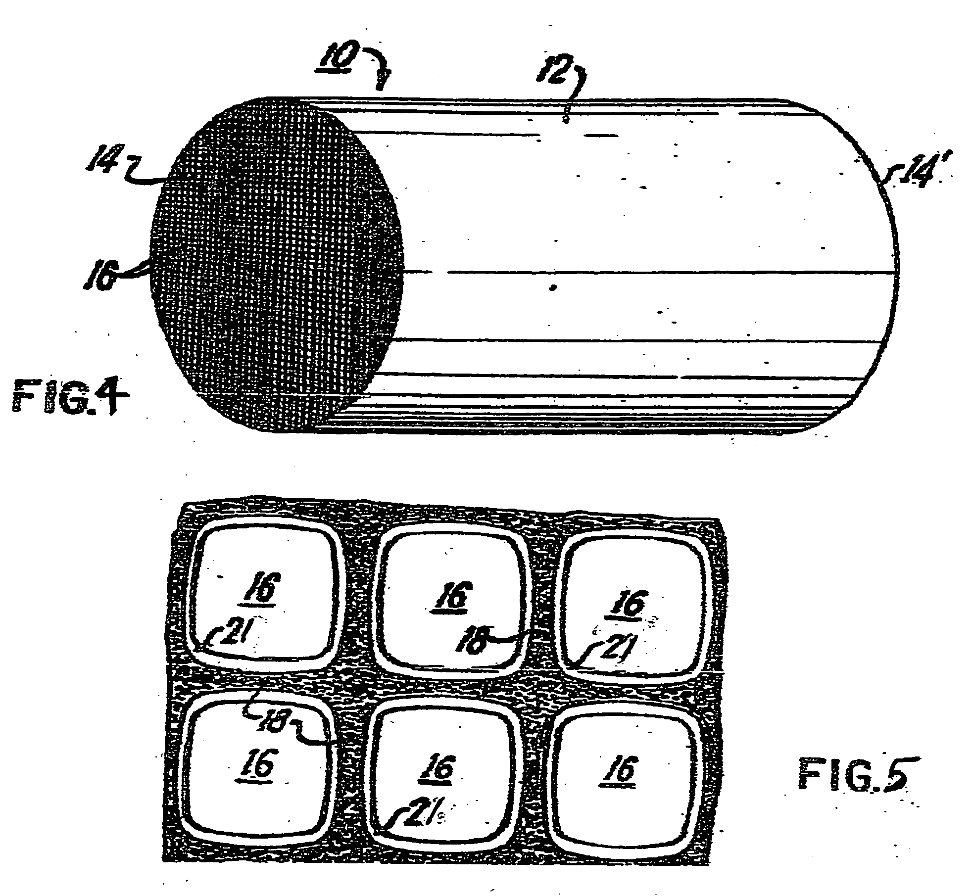
[0048]FIG. 4 shows generally at 10 a catalyst carrier illustrating a preferred embodiment of the present invention. The carrier is seen to be monolithic and of generally cylindrical shape having a cylindrical outer surface 12; one end face (inlet) 14 and an opposite end face, not visible in FIG. 4, which is identical to end face 14. The juncture of outer surface 12 with the opposite end face at its peripheral edge portion is indicated at 14′ in FIG. 1. Carrier 10 has a plurality of fluid flow channels formed therein, and, since a preferred embodiment of the present invention is adapted for the treatment of engine exhaust gases, these channels are referred to as gas flow channels 16, better seen in enlarged FIG. 5. Channel walls 21 form gas flow channels 16. Gas flow channels 16 extend through carrier 10 from end face 14 to the opposite end face thereof, the channels being unobstructed so as to permit the flow of a fluid, e.g., a gas, longitudinally through carrier 10 via gas flow channels 16 thereof. As may be seen from FIGS. 5 and 6, channel walls 21 are dimensioned and configured such that gas flow channels 16 have substantially regular polygonal shape, square in the illustrate embodiment, except for fillet portions 20 which, in the illustrated embodiment, define in profile arcuate concave sections and comprise the juncture of adjacent ones of walls 18.

Problems solved by technology

As the TWC catalyst ages, however, its ability to store oxygen diminishes and the efficiency of the catalytic converter decreases.
Contemporary catalytic converters have a significant oxygen storage capacity that dampens out the normal air / fuel cycling used in engine controller strategies.
Alteration of the oxygen storage capacity of typical catalysts, however, can alter the catalysts' characteristics including their conversion efficiency.
An increase or decrease in oxygen storage capacity to meet the OBD monitoring requirement can therefore be a burdensome process that can require multiple trials to finally arrive at the optimum oxygen storage capacity for a given exhaust system without sacrificing or altering catalytic efficiency or performance.
It is often the case that the final optimized formulation of a one catalyst that successfully meets the requirements of one exhaust platform having a specific oxygen storage capacity requirement, cannot be used for a different exhaust platform having a different oxygen storage capacity requirement without extensive reformulation and performance testing.

Method used


Image

  • Exhaust gas treatment catalyst
  • Exhaust gas treatment catalyst
  • Exhaust gas treatment catalyst

Examples


example 1

[0081] A catalyst was prepared in the following manner:

[0082] A cylindrical cordierite honeycomb substrate was used as the carrier. The carrier had a diameter of 4.16 inches, a length of 3.82 inches and a total volume of 52 in3. The total PGM content of the catalyst was 40 g / ft3. The PGM components consisted of platinum, palladium and rhodium in a ratio of 2:28:10, respectively.

[0083] A bottom (i.e., the first) layer was applied to the surface of the carrier by immersing the carrier in an approximately 35% solid content aqueous slurry containing 800 g gamma-alumina, 50 g alumina binder and 100 g of a composite of 92% zirconia and 8% lanthana. The thus-coated carrier was then calcined at 430° C. for 2 hours to obtain a dried washcoat at approximately 0.95 g / in3.

[0084] A middle (i.e., the second) layer in the form of an aqueous solution was then applied to the surface of the coated carrier. The middle layer consisted of an approximately 38% solid content, aqueous solution containin...

example 2

[0087] Example 1 was repeated, except that the top layer and overcoat layer formulations were reversed. That is, the overcoat formulation recited in Example 1 was applied to the surface of the middle layer. After calcination, the top layer formulation of Example 1 was applied to the surface of the resultant carrier that was then calcined at 500° C. for 2 hours.

example 3

[0088] The catalysts of Examples 1 and 2 were evaluated on a 2.2-liter, 4-cylinder vehicle in accordance with Federal Test Protocol #75. Hydrocarbon and NOx emission (grams per mile) data were gathered for each catalyst for three phases: cold start, cruising and hot start. The results for each phase are set forth below in the following table.


PUM

PropertyMeasurementUnit
BET specific surface areaaaaaaaaaaa
particle sizeaaaaaaaaaa
concentrationaaaaaaaaaa

Abstract

Provided are an exhaust treatment catalyst and an exhaust article containing the catalyst. The catalyst comprises: (a) a carrier; (b) a first layer deposited on the carrier, said first layer comprising substantially only at least one refractive metal oxide; (c) a second layer deposited on the first layer, said second layer comprising substantially only at least one oxygen storage component and at least one binder therefor; and (d) a third layer deposited on the second layer, said third layer comprising at least one layer of one or more platinum group metal components supported on a refractory metal oxide support. Optionally, a fourth layer is deposited on the third layer wherein the fourth layer comprises one or more platinum group metal components supported on a refractory metal oxide support. As a further option, an overcoat layer may be deposited on the third or fourth layer wherein the overcoat layer comprises a catalyst poison sorbent. Also provided are methods for preparing the catalyst and methods for monitoring the exhaust storage capacity of an exhaust article containing the catalyst.

Description

FIELD OF THE INVENTION [0001] The invention relates to an exhaust treatment catalyst and to an exhaust article containing the catalyst, as well as to methods for preparing the catalyst and the article and methods for their use in on-board diagnostic (“OBD”) systems. BACKGROUND OF THE INVENTION [0002] Three-way conversion (TWC) catalysts have utility in a number of fields including the treatment of exhaust from internal combustion engines, such as automobile and other gasoline-fueled engines. Emissions standards for unburned hydrocarbons, carbon monoxide and nitrogen oxides contaminants have been set by various governments and must be met, for example, by new automobiles. In order to meet such standards, exhaust articles containing a TWC catalyst are located in the exhaust gas line of internal combustion engines. The TWC catalysts promote the oxidation by oxygen in the exhaust gas of the unburned hydrocarbons and carbon monoxide and the reduction of nitrogen oxides to nitrogen. [0003...

Claims


Application Information

Patent Timeline
Patent Type & Authority Applications(United States)
IPC IPC(8): B01D53/00B01J23/40B01J23/58B01J23/63B01J35/04B01J37/02
CPCB01D53/945Y02T10/22B01D2255/1023B01D2255/1025B01D2255/204B01D2255/206B01D2255/20715B01D2255/2092B01D2255/407B01D2255/9027B01D2255/908B01D2255/9207B01J23/40B01J23/58B01J23/63B01J35/04B01J37/0244B01J37/0248B01D2255/1021Y02T10/12Y02A50/20B01D53/00
Inventor CHEN, SHAU-LIN FRANKLINHU, ZHICHENG
Owner BASF CATALYSTS LLC
Why Eureka
Try Eureka