Image formation apparatus

Inactive Publication Date: 2006-09-14
SHARP KK
View PDF14 Cites 2 Cited by
  • Summary
  • Abstract
  • Description
  • Claims
  • Application Information

AI Technical Summary

Benefits of technology

[0012] The image formation apparatus of this invention comprises: image formation means for forming color-component images that correspond to a plurality of color components onto a plurality of corresponding image-carrying bodies respectively; and a transfer medium onto which the respective color-component images that are formed on the image-carrying bodies are transferred; and where the image formation apparatus adjusts the image formation timing based on the positions of the respective color-component images that are transferred to the transfer medium; and when adjusting the image formation timing, the image formation means forms color-component images at formation intervals that correspond to an integral multiple of the period of a periodic noise. In this invention, when adjusting the image formation timing, the image formation means forms color-component images at formation intervals that correspond to an integral multiple of the period of a periodic noise, so the noise affecting the formed color-component images becomes uniform. Therefore, by taking into consideration noise, it is possible to adjust the image formation timing with high precision.
[0013] The image formation apparatus of this invention comprises: image formation means for forming color-component images that correspond to a plurality of color components onto a plurality of corresponding image-carrying bodies respectively; and a transfer medium onto which the respective color-component images that are formed on the image-carrying bodies are transferred; and where the image formation apparatus adjusts the image formation timing based on the positions of the respective color-component images that are transferred to the transfer medium; and the image-carrying bodies comprise gears to which a rotational movement is transferred; and when adjusting the image formation timing, the image formation means forms color-component images at formation intervals that correspond to an integral multiple of the tooth interval of the gears. In this invention, the image-carrying bodies comprise gears to which a rotational movement is transferred, and due to the tolerance and play between tooth of gears, periodic noise having a period that corresponds to the tooth interval of the gears affects the formation of color-component images, however, since the aforementioned formation interval corresponds to an integral multiple of the tooth interval of the gears, the noise affecting the formed color-component images becomes uniform. The noise from the gears of the image-carrying bodies can be made uniform, so by taking that noise into consideration, it is possible to adjust the image formation timing with high precision.
[0014] The image formation apparatus of this invention is constructed such that the image formation means changes the formation interval after each specified period. In this invention, the image formation means changes the formation interval after each specified period, so even when the aforementioned formation interval does not perfectly match the period of the periodic noise, it is still possible to prevent an accumulation of error. For example, when the formation interval is 4.1 times the periodic interval A of the noise, then normally the integral multiple is set to 4 times, and after every 10 periods, it is possible to substitute 5 times as the integral multiple in the place of 4 times (4Δ×9+5Δ=41Δ=4.1Δ×10). In this way, together with being able to flexibly set the formation interval, it is possible to prevent error between the formation interval and the integral multiple of the period of the noise from accumulating.
[0015] The image formation apparatus of this invention comprises: image formation means for forming color-component images that correspond to a plurality of color components onto a plurality of corresponding image-carrying bodies respectively; and a transfer medium o

Problems solved by technology

The timing for forming the marks is set mainly by the timing for outputting the laser beams, however, there is a problem in that misalignment of the formation position of the marks occurs due to fluctuation in the rpm of the photosensitive drums.
Als

Method used


Image

  • Image formation apparatus
  • Image formation apparatus
  • Image formation apparatus

Examples


Embodiment Construction

[0032] The present invention will be described in detail below based on drawings showing the preferred embodiments.

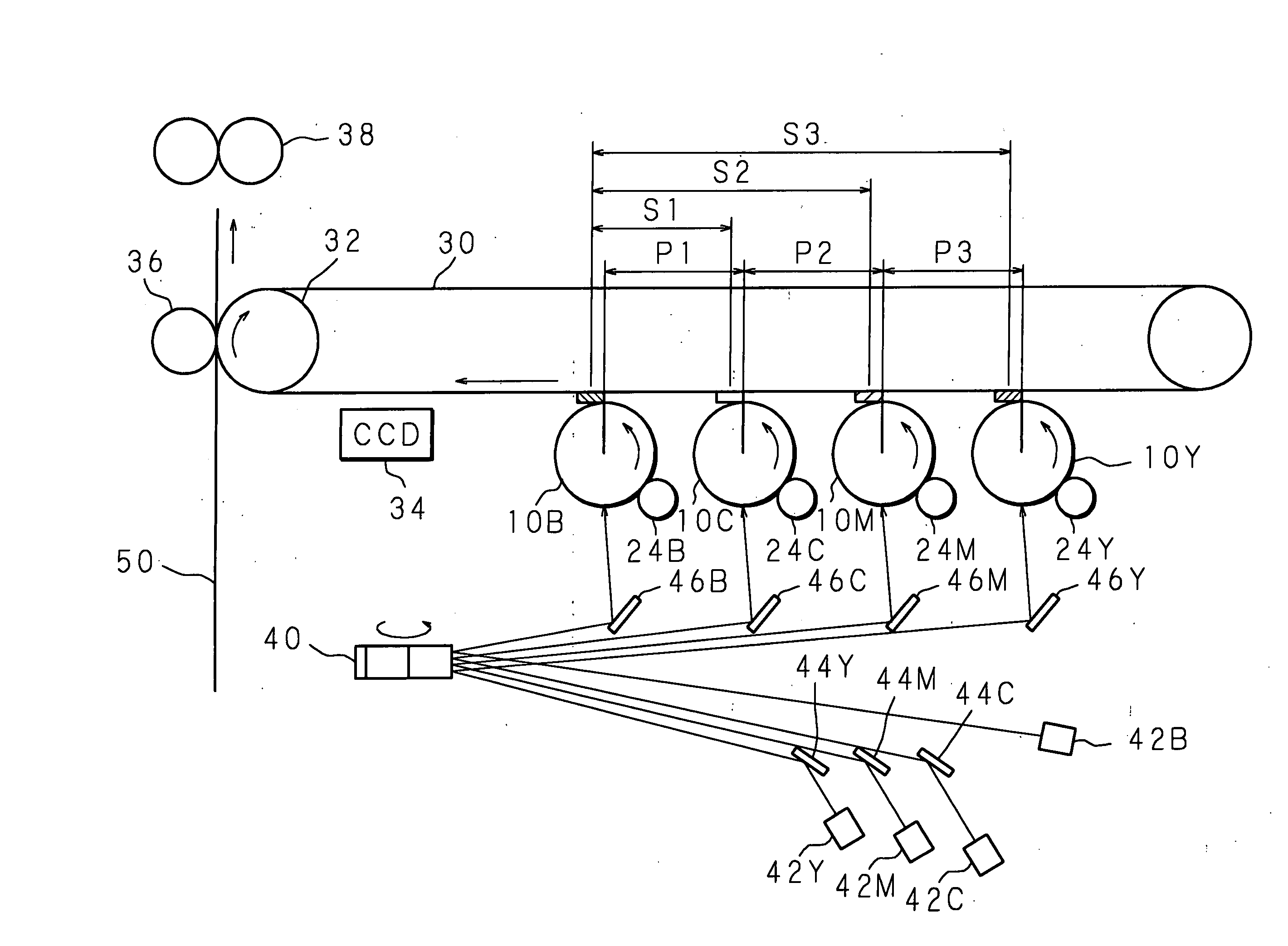
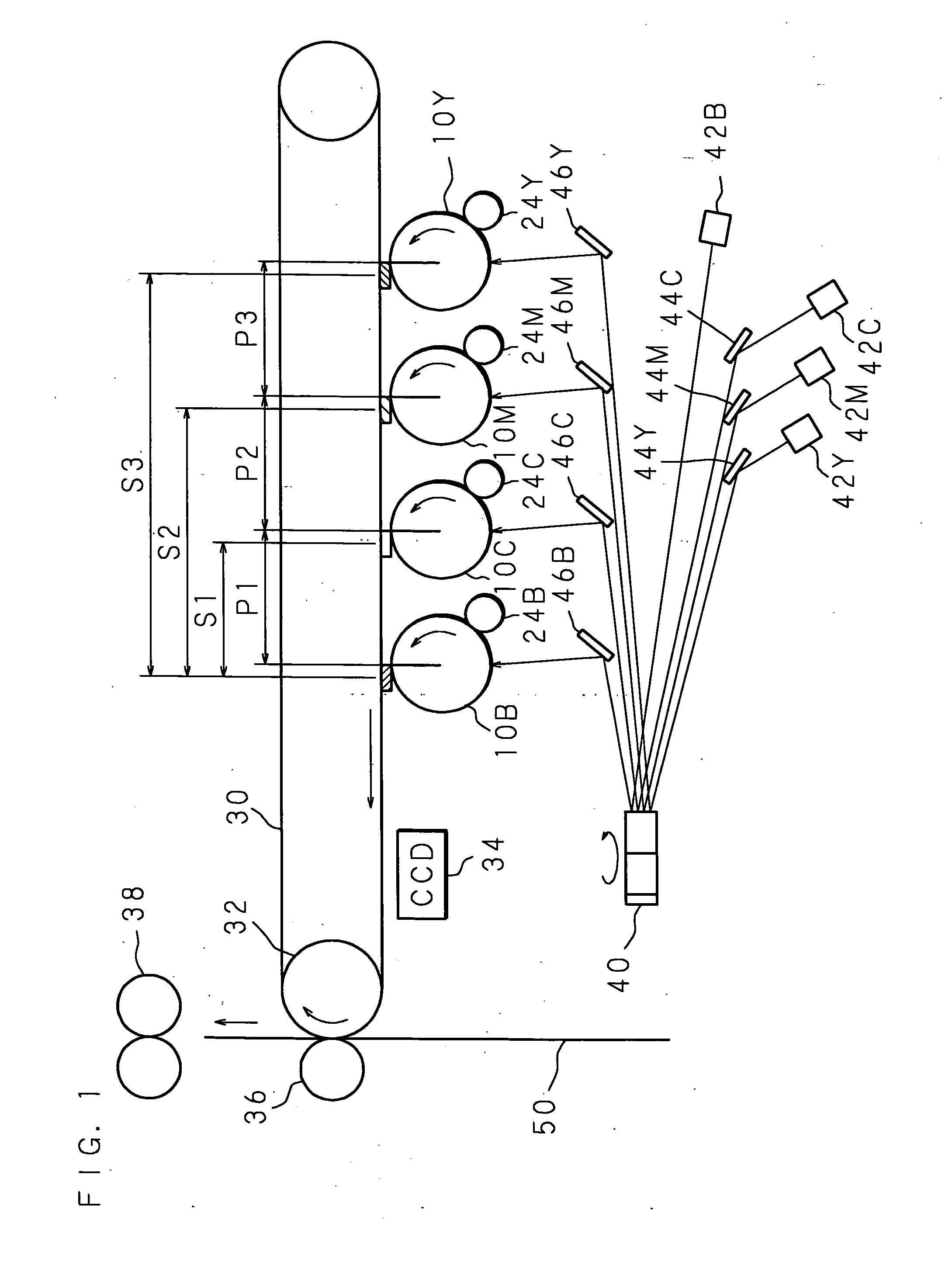
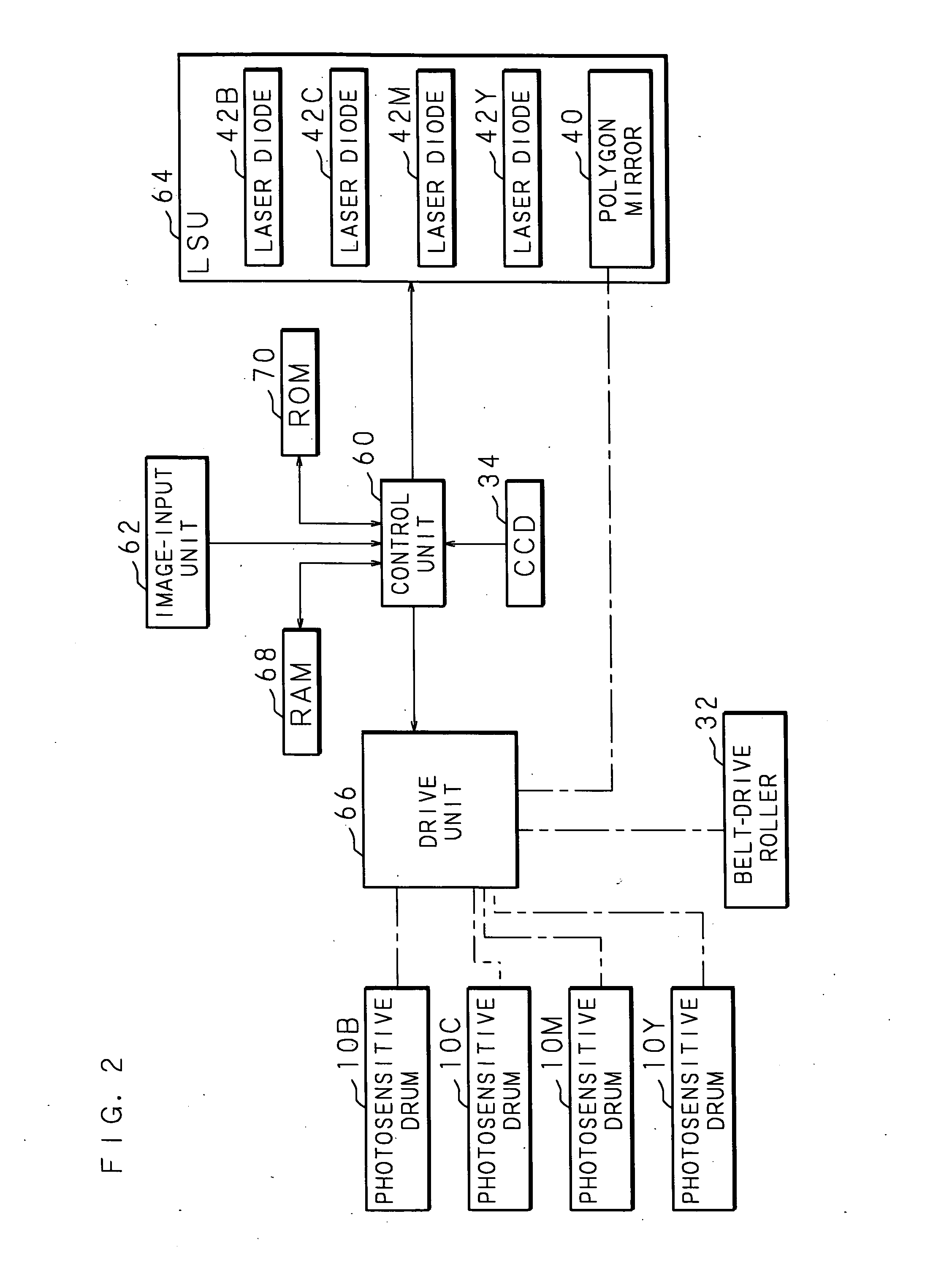
[0033]FIG. 1 is a drawing showing the major parts of the image formation apparatus of the invention. The image formation apparatus comprises as major components: photosensitive drums (image-carrying bodies) 10 on which images are formed; laser diodes (irradiation means) 42 that output laser beams (light beams); first mirrors 44, polygon mirror 40 and second mirrors 46 that direct the laser beams that are outputted from the laser diodes 42 to the photosensitive drums 10; developer rollers 24 that develop the latent images that are formed on the photosensitive drums 10 by laser beams; and a transfer belt (transfer medium) 30 onto which the images formed on the photosensitive drums 10 are transferred.

[0034] The photosensitive drums 10 include a photosensitive drum 10B for black, a photosensitive drum 10C for cyan, a photosensitive drum 10M for magenta and a photosensitiv...


PUM


Abstract

An image formation apparatus that comprises: a plurality of laser diodes that form color-component images that correspond to a plurality of color components onto a plurality of corresponding photosensitive drums respectively; and a transfer belt onto which the color-component images that are formed on the respective photosensitive drums are transferred; and adjusts the image formation timing based on the positions of the color-component images that are transferred to the transfer belt; and when adjusting the image formation timing, the respective laser diodes form color-component images at formation intervals that correspond to an integral multiple of the period of a periodic noise. Adjustment of the image formation timing is performed at high precision.

Description

CROSS-REFERENCE TO RELATED APPLICATIONS [0001] This Non-provisional application claims priority under 35 U.S.C. §119(a) on Patent Application No. 2005-64292 filed in Japan on Mar. 8, 2005, the entire contents of which are hereby incorporated by reference. BACKGROUND OF THE INVENTION [0002] This invention relates to an image formation apparatus comprising: image formation means for forming color-component images corresponding to a plurality of color components onto a plurality of image-carrying bodies respectively that correspond to the respective color components; and a transfer medium onto which the respective color components formed on the image-carrying bodies are transferred; and adjusts the timing for forming an image based on the positions of the respective color-component images that are transferred to the transfer medium. [0003] There are image formation apparatuses for forming color images on paper that form color-component images onto respective photosensitive drums for bl...

Claims


Application Information

Patent Timeline
IPC IPC(8): B41J2/01
CPCB41J2/0057
Inventor MATSUYAMA, KENGO
Owner SHARP KK
Why Eureka
Try Eureka