Machine tool holder having internal coolant supply and cutter retaining and coolant distribution cutter insert retaining clamp assembly

a technology of cutter inserts and clamp assemblies, which is applied in the direction of cutting inserts, manufacturing tools, turning machine accessories, etc., can solve the problems of mounting coolant supply tubes, difficult to efficiently support coolant supply tubes or hoses, and difficulty in ensuring the immediate supply of coolant fluid, so as to minimize heat induced wear and deterioration of metal cutting inserts, and enhance service life

Inactive Publication Date: 2007-12-13
GIANNETTI ENRICO R
View PDF5 Cites 98 Cited by
  • Summary
  • Abstract
  • Description
  • Claims
  • Application Information

AI Technical Summary

Benefits of technology

[0020]The clamp member defines one or more internal coolant fluid flow passages that terminate at one or more discharge openings located on the clamp member. The discharge opening or openings are each located and oriented to direct a discharge or jet of coolant fluid onto the metal cutting insert immediately at the site of its metal cutting operation within the rotating work-piece. In the preferred embodiment of the invention the clamp screw defines an internal passage that is in communication with the transverse coolant fluid flow passage and conducts coolant fluid to the internal coolant fluid flow passage or passages of the clamp member for precise distribution of coolant flow to the metal cutting insert. In a further alternative embodiment of the invention, an annular clearance is defined about the shank of the clamp screw and which serves as a flow passage. This annular flow passage is in fluid communication with the internal coolant fluid discharge passage or passages of the clamp or coolant fluid distribution nozzle member. The coolant fluid distributing nozzle defines an internal coolant flow passage having an exit or discharge opening directed immediately at the site of metal cutting by the insert and thus maintains the metal cutting insert as cool as possible during boring operations. The coolant minimizes heat induced wear and deterioration of the metal cutting insert and thus enhances its service life.
[0021]The cutter support head of the machine tool holder of the present invention is also machined to provide a coolant fluid distribution passage and opening that directs a jet of coolant fluid in a manner for flushing away metal chips and preventing an accumulation of metal chips or cuttings that might otherwise interfere with the efficiency and accuracy of a metal cutting operation. The chip flushing coolant discharge opening of the cutter support head may be provided with a removable jet nozzle, thus permitting the character of the chip flushing jet of high pressure coolant to be changed simply by substituting a larger or smaller jet nozzle for a particular jet nozzle being used.

Problems solved by technology

When metal cutting operations are carried out by a boring bar internally of a rotating work-piece, such as is the case when boring operations are being carried out, the boring bar being used can have considerable length, thus making it difficult to efficiently support a coolant supply tube or hose and conduct an adequate supply of coolant fluid to the immediate region of the metal cutting insert of the boring bar.
In the case of some machine tools of considerable length, such as boring bar tools, it is difficult to mount coolant supply tubes to the tools; thus adequate cooling of cutter inserts is not efficiently achieved.
Positioning coolant supply tubes on or near cutting tools often obscures the metal cutting site to the point that visual inspection of the metal cutting operation is impaired.
Also, the use of mounts to provide clamping or retaining support for replaceable metal cutting inserts and additional mounts to support one or more coolant nozzles on machine tools typically makes the machine tools quite complex and expensive.
When high pressure application of coolant to a metal cutting interface is needed, tubes for conducting the coolant to the metal cutting interface are often impractical especially when long tube lengths are also needed.

Method used


Image

  • Machine tool holder having internal coolant supply and cutter retaining and coolant distribution cutter insert retaining clamp assembly
  • Machine tool holder having internal coolant supply and cutter retaining and coolant distribution cutter insert retaining clamp assembly
  • Machine tool holder having internal coolant supply and cutter retaining and coolant distribution cutter insert retaining clamp assembly

Examples


Embodiment Construction

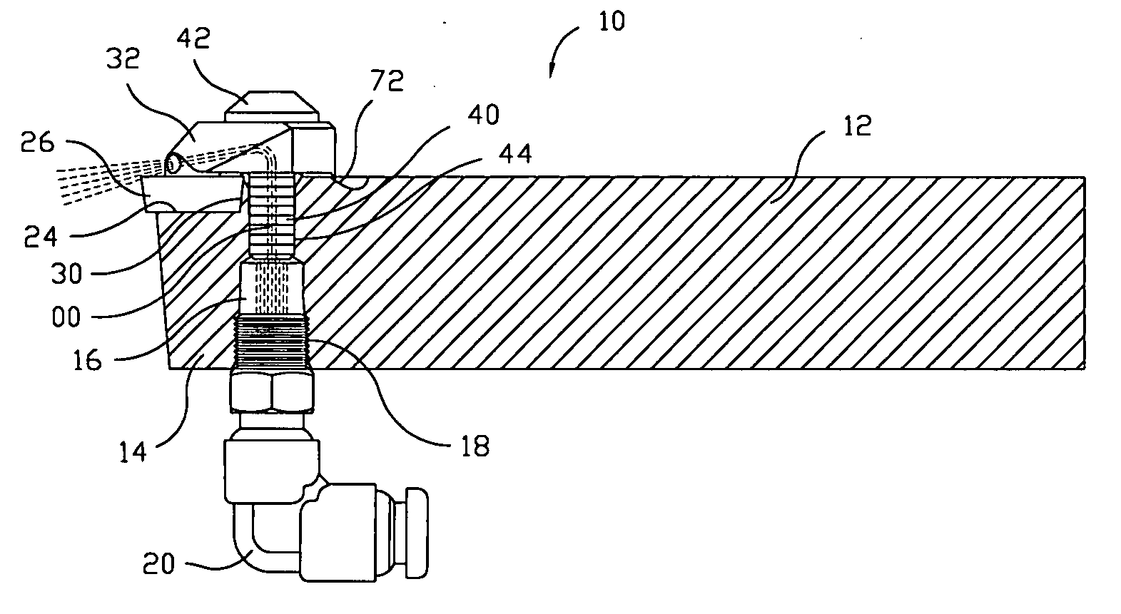
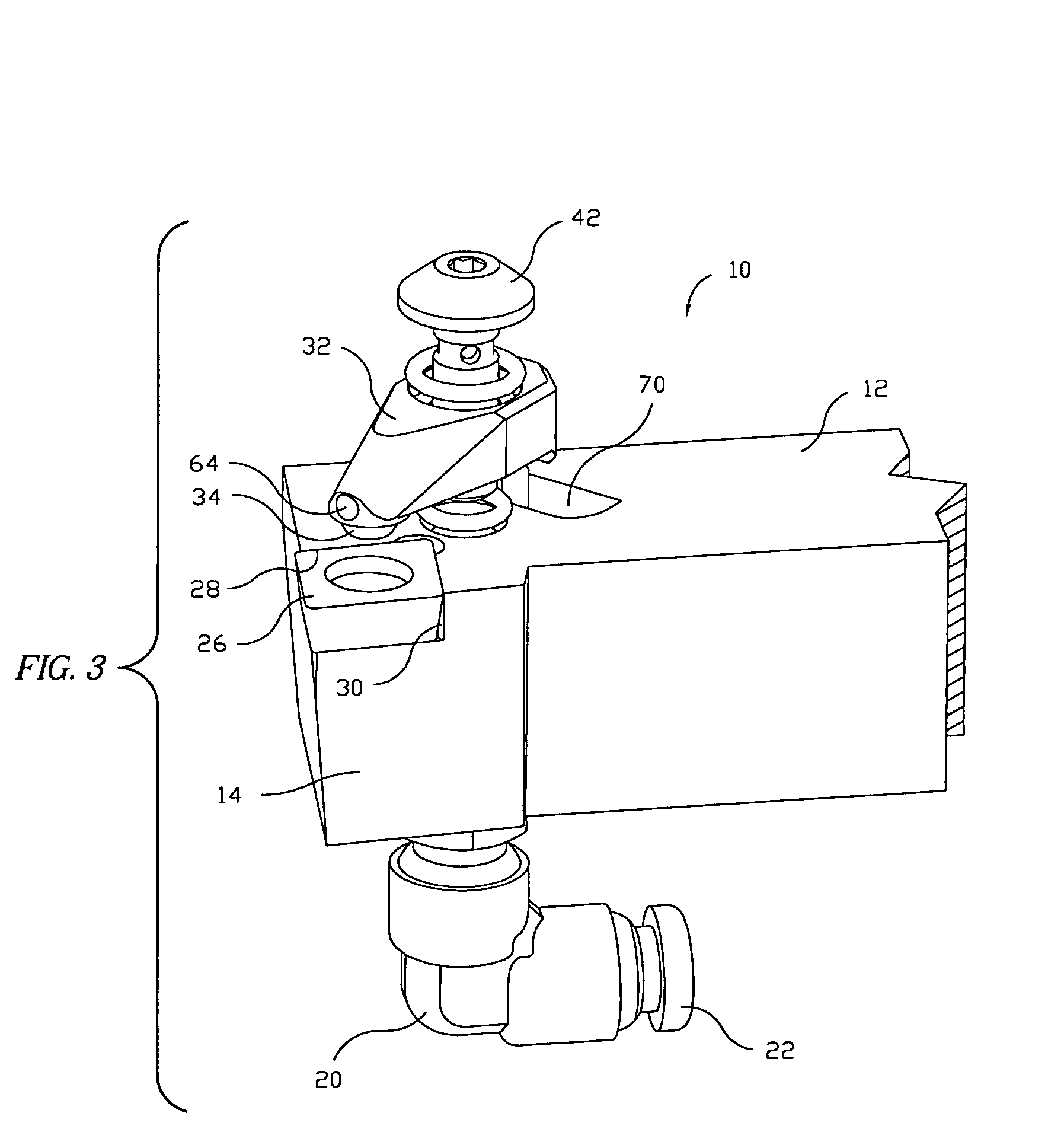
[0064]For purposes of simplicity, the present invention is discussed herein particularly with respect to its form as a boring bar for cutting or boring operations on the interior of a work-piece being rotated by a metal working machine. However, it is to be understood that the present invention has application to a wide range of machine tool holders for external as well as internal machining operations; thus this specification is to be intended as descriptive of a wide range of cutter support machine tools and is not as intended as restricting the spirit and scope of the invention to boring bars or any other type of cutter supporting machine tools.

[0065]Referring now to the drawings and first to FIGS. 1-3 a coolant fluid supplying machine tool or cutter insert holder, such as a boring bar, is shown generally at 10, having an elongate tool shank 12 with cutter insert support head 14 at one end thereof and representing a preferred embodiment of the present invention. The cutter insert...


PUM

PropertyMeasurementUnit
pulling forceaaaaaaaaaa
compressive deformationaaaaaaaaaa
structureaaaaaaaaaa

Abstract

A boring bar has a shank having a cutter support head at one end. A flow passage extends to the cutter support head and intersects a transverse flow passage that is defined in part by a clamp screw passage of the head. A metal cutting insert is clamped to the cutter support head by a clamp that is secured by a clamp screw being threaded into the clamp screw passage. The clamp screw defines an internal or external passage that communicates with the internal coolant fluid passage and completes a coolant distribution circuit. The clamp defines an internal coolant fluid passage having a discharge opening located and oriented to direct a jet of coolant fluid onto the metal cutting insert immediately at the site of cutting engagement within the rotating workpiece. The cutter support head also has a passage and chip removal jet nozzle that orients a jet of coolant fluid adjacent the cutter insert for remove metal chips during machining.

Description

[0001]This is a Continuation-in-Part application based on pending application Ser. No. 11 / 452,154 which was filed on Jun. 13, 2006 by Enrico R. Giannetti and entitled “Boring Bar Having Internal Coolant Supply And Cutter Retaining Nozzle”.BACKGROUND OF THE INVENTION[0002]1. Field of the Invention[0003]The present invention relates generally to machine tool holders such as boring bars that are mounted to machine tools and are used for external machining operations or for boring internal surfaces in work pieces that are typically rotated by a machine tool. More particularly the present invention pertains to machine tool holders such as boring bars having an internal coolant supply to discharge a liquid coolant and cutting fluid medium immediately at the site of metal cutting by a metal cutting insert of a machine tool holder. Even more specifically, a coolant fluid distributing nozzle also functions as a clamp for releasably securing a metal cutting insert to the cutter support head o...

Claims


Application Information

Patent Timeline
Patent Type & Authority Applications(United States)
IPC IPC(8): B23B29/00B32B29/00
CPCB23B27/10B23B27/1644B23B2200/088Y10T82/2585B23B2260/03B23B2260/124B23B2270/30B23B2250/12
Inventor GIANNETTI, ENRICO R.
Owner GIANNETTI ENRICO R
Why Eureka
Try Eureka