Boring bar having internal coolant supply and cutter retaining nozzle

a technology of coolant supply and bore, which is applied in the direction of cutting inserts, manufacturing tools, shaping cutters, etc., can solve the problems of reducing the service life of the metal cutting insert. , to achieve the effect of enhancing the service life and minimizing the heat induced wear and deterioration of the metal cutting inser

Inactive Publication Date: 2007-12-13
GIANNETTI ENRICO R
View PDF5 Cites 40 Cited by
  • Summary
  • Abstract
  • Description
  • Claims
  • Application Information

AI Technical Summary

Benefits of technology

[0016]Briefly, the various objects and features of the present invention are realized through the provision of a machine tool such as a boring bar having an elongate shank having an integral cutter support head structure at one end. A coolant fluid flow passage extends longitudinally through the shank of the machine tool to the cutter support head and intersects a transverse coolant fluid flow passage which is defined in part by a clamp screw passage. Alternatively, the coolant fluid flow passage can be provided only in the head portion of the tool, with a coolant supply line of the tool being connected to the tool head. In accordance with the preferred embodiment and best mode of the present invention, a coolant distribution nozzle is mounted to the head of the tool by a mounting bolt and the nozzle and its mounting bolt provide for coolant distribution to the metal cutting interface and also provide a clamping function for retaining a metal cutting insert in proper position on the tool head for optimum machining. Alternatively, a replaceable metal cutting insert is clamped to the cutter support head structure by a clamp member that is secured by a clamp screw being threaded into the clamp screw passage. The clamp screw, and its association with the cutter support head structure, cooperate to define an internal or external flow passage permitting fluid flow transition from the longitudinal boring bar flow passage and through the head and clamp structures. The clamp member defines one or more internal coolant fluid flow passages that terminate at one or more discharge openings located on the clamp member. The discharge opening or openings are each located and oriented to direct a discharge or jet of coolant fluid onto the metal cutting insert immediately at the site of its metal cutting operation within the rotating work-piece. In the preferred embodiment of the invention the clamp screw defines an internal passage that is in communication with the transverse coolant fluid flow passage and conducts coolant fluid to the internal coolant fluid flow passage or passages of the clamp member for precise distribution of coolant flow to the metal cutting insert. In a further alternative embodiment of the invention, an annular clearance is defined about the shank of the clamp screw and which serves as a flow passage. This annular flow passage is in fluid communication with the internal coolant fluid discharge passage or passages of the clamp or coolant fluid distribution nozzle member. The coolant fluid distributing nozzle defines an internal coolant flow passage having an exit or discharge opening directed immediately at the site of metal cutting by the insert and thus maintains the metal cutting insert as cool as possible during boring operations. The coolant minimizes heat induced wear and deterioration of the metal cutting insert and thus enhances its service life.
[0017]The cutter head of the machine tool holder of the present invention is also machined to provide a coolant fluid distribution passage and opening that directs a jet of coolant fluid in a manner for flushing away metal chips and preventing an accumulation of metal chips or cuttings that might otherwise interfere with the efficiency and accuracy of a metal cutting operation.

Problems solved by technology

When metal cutting operations are carried out by a boring bar internally of a rotating work-piece, such as is the case when boring operations are being carried out, the boring bar being used can have considerable length, thus making it difficult to efficiently support a coolant supply tube or hose and conduct an adequate supply of coolant fluid to the immediate region of the metal cutting insert of the boring bar.
In the case of some machine tools of considerable length, such as boring bar tools, it is difficult to mount coolant supply tubes to the tools; thus adequate cooling of cutter inserts is not efficiently achieved.
Positioning coolant supply tubes on or near cutting tools often obscures the metal cutting site to the point that visual inspection of the metal cutting operation is impaired.
Also, the use of mounts to provide clamping or retaining support for replaceable metal cutting inserts and additional mounts to support one or more coolant nozzles on machine tools typically makes the machine tools quite complex and expensive.

Method used


Image

  • Boring bar having internal coolant supply and cutter retaining nozzle
  • Boring bar having internal coolant supply and cutter retaining nozzle
  • Boring bar having internal coolant supply and cutter retaining nozzle

Examples


Embodiment Construction

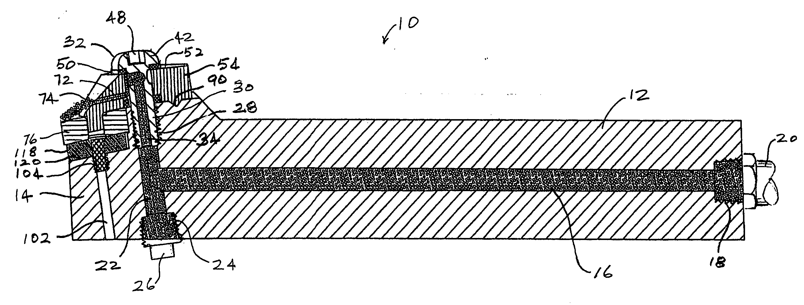
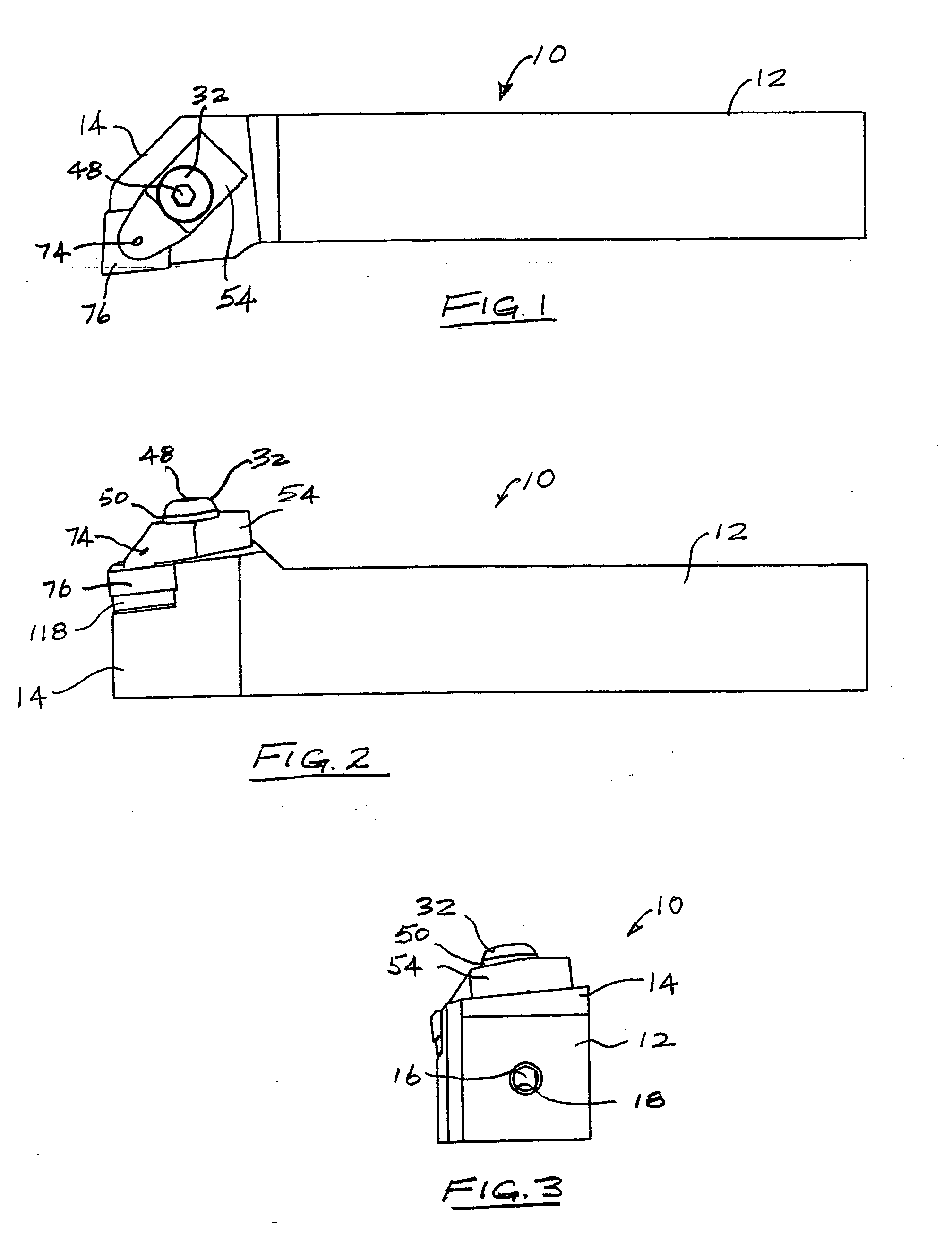
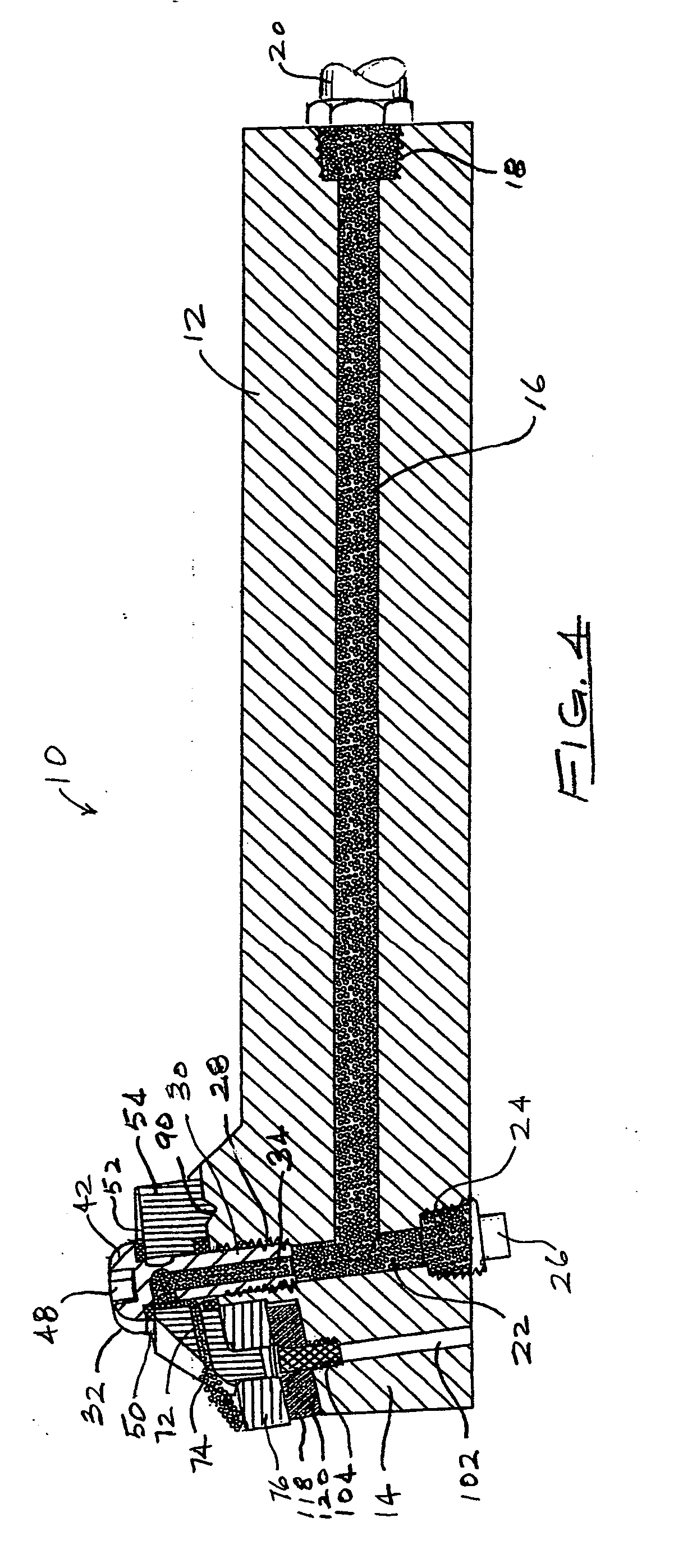
[0040]For purposes of simplicity, the present invention is discussed herein particularly with respect to its form as a boring bar for cutting or boring the interior of a rotating work-piece. However, it is to be understood that the present invention has application to a wide range of machine tool holders; thus this specification is to be intended as descriptive of preferred embodiments of the invention and not as restricting the spirit and scope of the invention. Also, while the coolant medium is referred to as a fluid, it is intended that the coolant fluid medium may comprise a liquid or liquid mixture or air or any suitable gaseous medium. Referring now to the drawings and first to FIGS. 1-3 a coolant fluid supplying machine tool holder such as a boring bar is shown generally at 10, having a coolant fluid flow passage therein and representing a preferred embodiment of the present invention. The boring bar 10 comprises an elongate shank 12 having a coolant supplying cutter support ...


PUM

PropertyMeasurementUnit
pulling forceaaaaaaaaaa
temperatureaaaaaaaaaa
lengthaaaaaaaaaa

Abstract

A boring bar has a shank having a cutter support head at one end. A flow passage extends longitudinally through the shank to the cutter support head and intersects a transverse flow passage that is defined in part by a clamp screw passage of the head. A metal cutting insert is clamped to the cutter support head by a clamp that is secured by a clamp screw being threaded into the clamp screw passage. The clamp member defines at least one coolant fluid flow passage having a discharge opening or openings each located and oriented to direct a jet of coolant fluid onto the metal cutting insert immediately at the site of cutting engagement within the rotating workpiece. The clamp screw defines an internal passage that communicates with the transverse coolant fluid flow passage and conducts coolant fluid onto the metal cutting insert. Alternatively, an annular clearance is defined about the shank of the clamp screw and serves as a coolant flow passage which is in fluid communication with the internal coolant fluid discharge passage or passages of the clamp member.

Description

[0001]This is a Continuation-in-Part application based on pending application Ser. No. ______ which was filed on Dec. 29, 2004 by Enrico R. Giannetti and is entitled “Boring Bar Having Internal Coolant Supply”.BACKGROUND OF THE INVENTION[0002]1. Field of the Invention[0003]The present invention relates generally to machine tool holders such as boring bars that are mounted to machine tools and are used for external machining operations or for boring internal surfaces in work pieces that are typically rotated by a machine tool. More particularly the present invention pertains to machine tool holders such as boring bars having an internal coolant supply to discharge a liquid coolant and cutting fluid medium immediately at the site of metal cutting by a metal cutting insert of a machine tool holder. Even more specifically, a coolant fluid distributing nozzle also functions as a clamp for releasably securing a metal cutting insert to the cutter support head of a boring bar or other machi...

Claims


Application Information

Patent Timeline
Patent Type & Authority Applications(United States)
IPC IPC(8): B23P15/28
CPCB23B27/10B23B27/1644B23B2200/088Y10T407/14B23B2260/03B23B2270/30B23B2250/12
Inventor GIANNETTI, ENRICO R.
Owner GIANNETTI ENRICO R
Why Eureka
Try Eureka