Air conditioning apparatus

a technology for air conditioning apparatus and chiller, which is applied in the direction of domestic cooling apparatus, lighting and heating apparatus, heating types, etc., can solve the problems of increasing the load of the chiller, and affecting the comfort of the person, so as to reduce the amount of consumed energy, prevent the increase of the chiller load, and save energy to be consumed by the air conditioning apparatus as a whole system

Inactive Publication Date: 2007-05-17
HITACHI LTD
View PDF3 Cites 90 Cited by
  • Summary
  • Abstract
  • Description
  • Claims
  • Application Information

AI Technical Summary

Benefits of technology

[0026] The air conditioning apparatus of the present invention can provide a merit that increase in the chiller load can be prevented, because both indoor temperature and humidity can be adjusted respectively to the set points by heat exchange only in one cooling coil through adequate adjustment of the ratio of the dry coil part and wet coil part of the cooling coil, by controlling the temperature of the coolant supplied to the cooling coil, the coolant flow rate of the cooling coil, and the air flow rate of the blower.
[0027] Moreover, energy to be consumed by the air conditioning apparatus as a whole system can be saved through operation using a combination to minimize the amount of consumed energy among the combinations of each of the set points of the temperature of the coolant supplied to the cooling coil, the coolant flow rate to the cooling coil, and the air flow rate to be blown by the blower.
[0028] Moreover, the air conditioning apparatus of the present invention can also provide a merit that the reheating coil is not needed, because reheating process is not required and thereby the apparatus itself can be reduced in size.

Problems solved by technology

However, in air conditioning for business offices or home, humidity is often left to chance, although the temperature is controlled in accordance with the set point.
For example, under high humidity ambient, even if temperature is adequately controlled, a person feels discomfort.
However, the method explained above not only allows increase in the load of the chiller 4 because of excessive cooling but also requires a heat source for reheating.
Therefore, here rises a problem that useless energy is doubly consumed by cooling and reheating processes.
However, the related arts described above have the following problems.
A framework disclosed by the patent document 1 has a problem that the increase of the chiller load by an excessive cooling cannot be reduced, although a especially prepared heat source is not required for reheating.

Method used


Image

  • Air conditioning apparatus
  • Air conditioning apparatus
  • Air conditioning apparatus

Examples


first embodiment

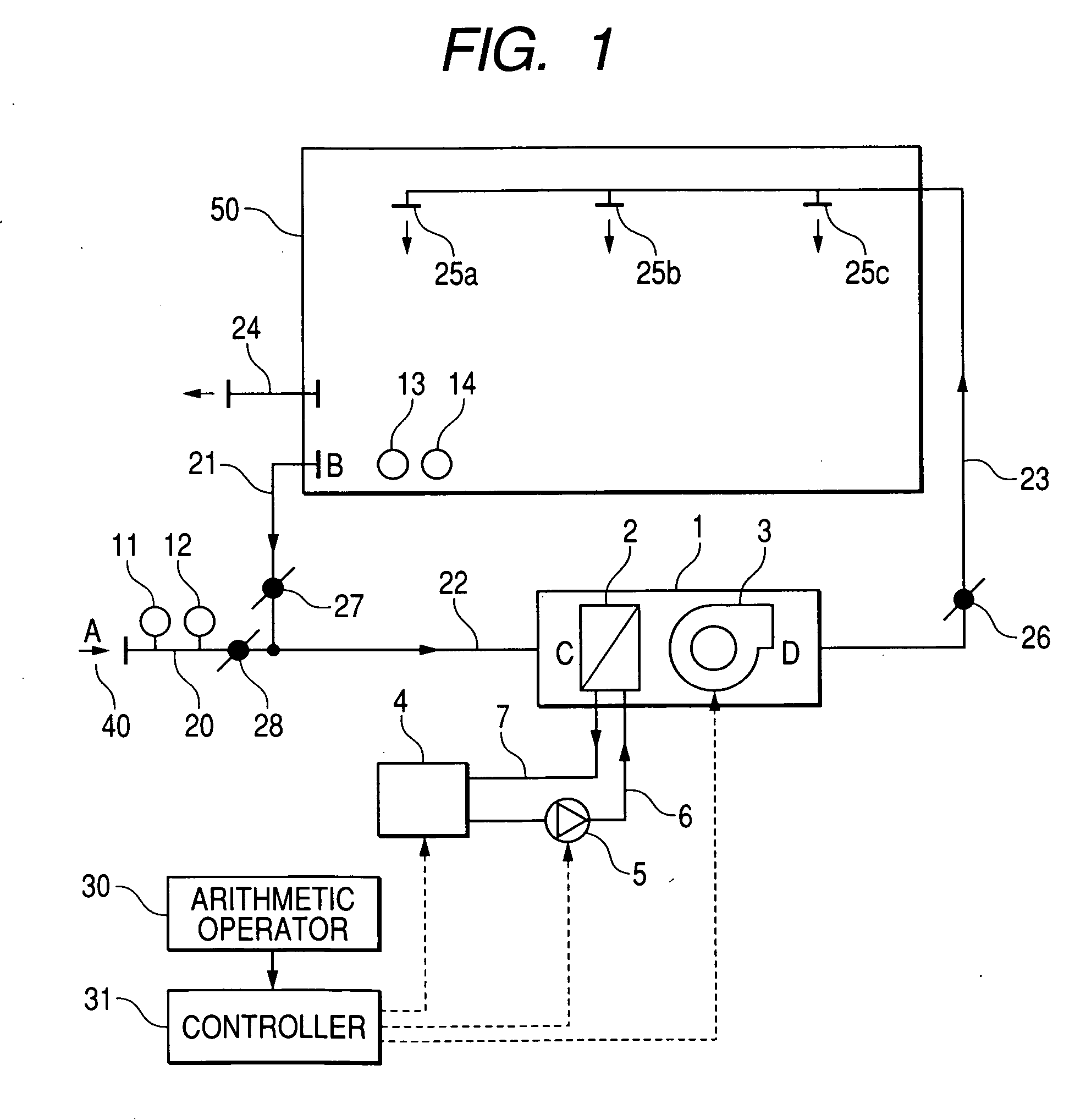
[0041]FIG. 1 is a block diagram showing a structure of an air conditioning apparatus for explaining the first embodiment according to the present invention. The first embodiment shown in FIG. 1 is composed of a line for supplying air and a line for supplying chilled water as a coolant. The line for air is composed of an outdoor air duct 20 for taking outdoor air 40, an air returning duct 21 for returning the air from a room, an intake duct 22 for supplying outdoor air or return air to an air-conditioning unit 1 connected to the outdoor air duct 20 and the return air duct 21, the air-conditioning unit 1 comprising a cooling coil 2 and a blower 3, a supply air duct 23 for guiding air exhausted from the air-conditioning unit 1 into the room, a plurality of air supply openings 25 provided within the room, and an exhausting duct 24 for exhausting the air in the room to the outside thereof.

[0042] The outdoor air duct 20 includes an outdoor air damper 28, while the return air duct 21 incl...

second embodiment

[0069] A second embodiment according to an aspect of the present invention will be explained with reference to FIGS. 9 to 11. FIG. 9 is a block diagram showing a structure of the air conditioning apparatus for explaining the second embodiment of the present invention. FIG. 10 is a block diagram for explaining the second embodiment of the present invention. Moreover, FIG. 11 is a flowchart for explaining the operations of an arithmetic unit in the second embodiment of the present invention.

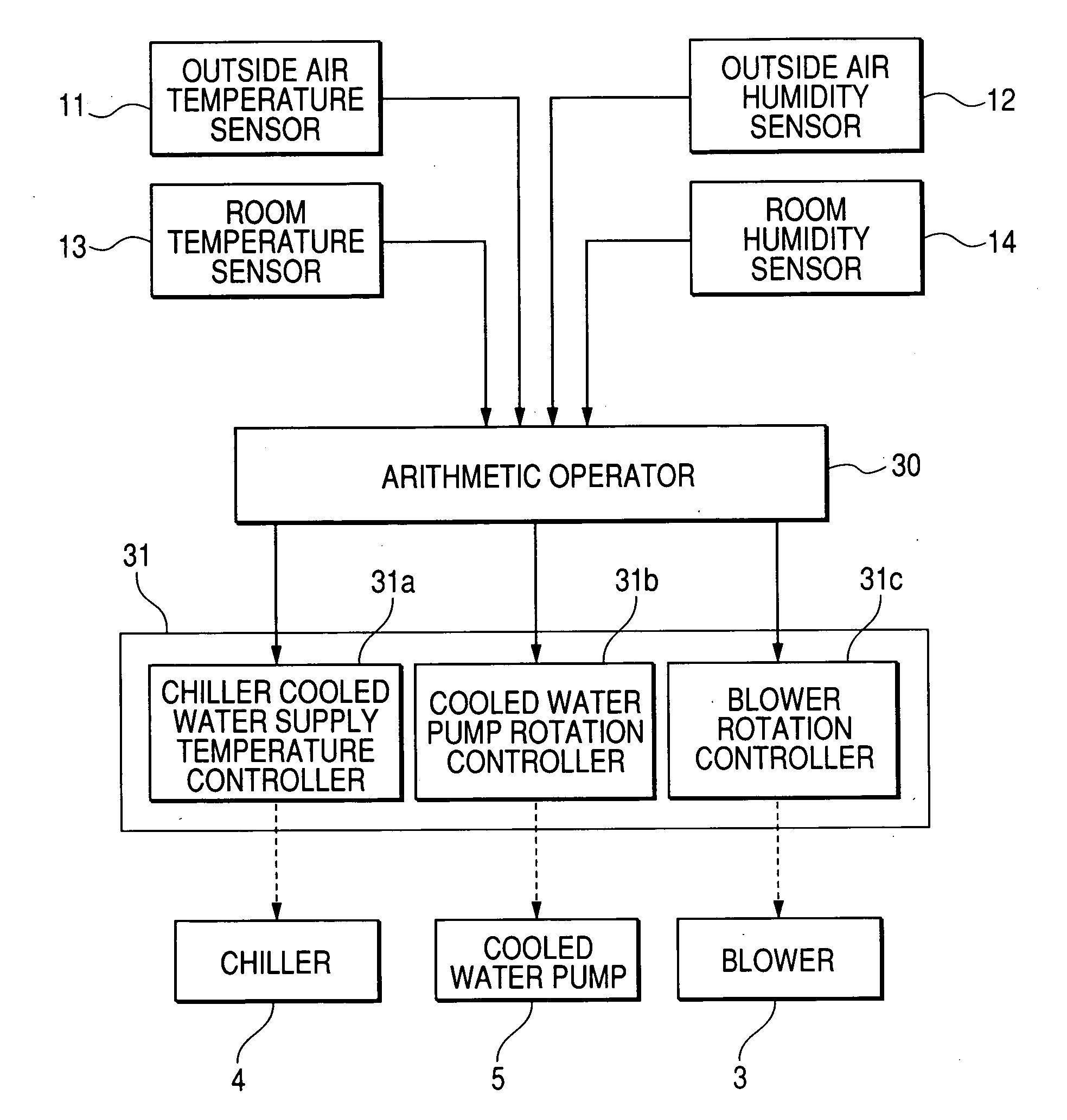
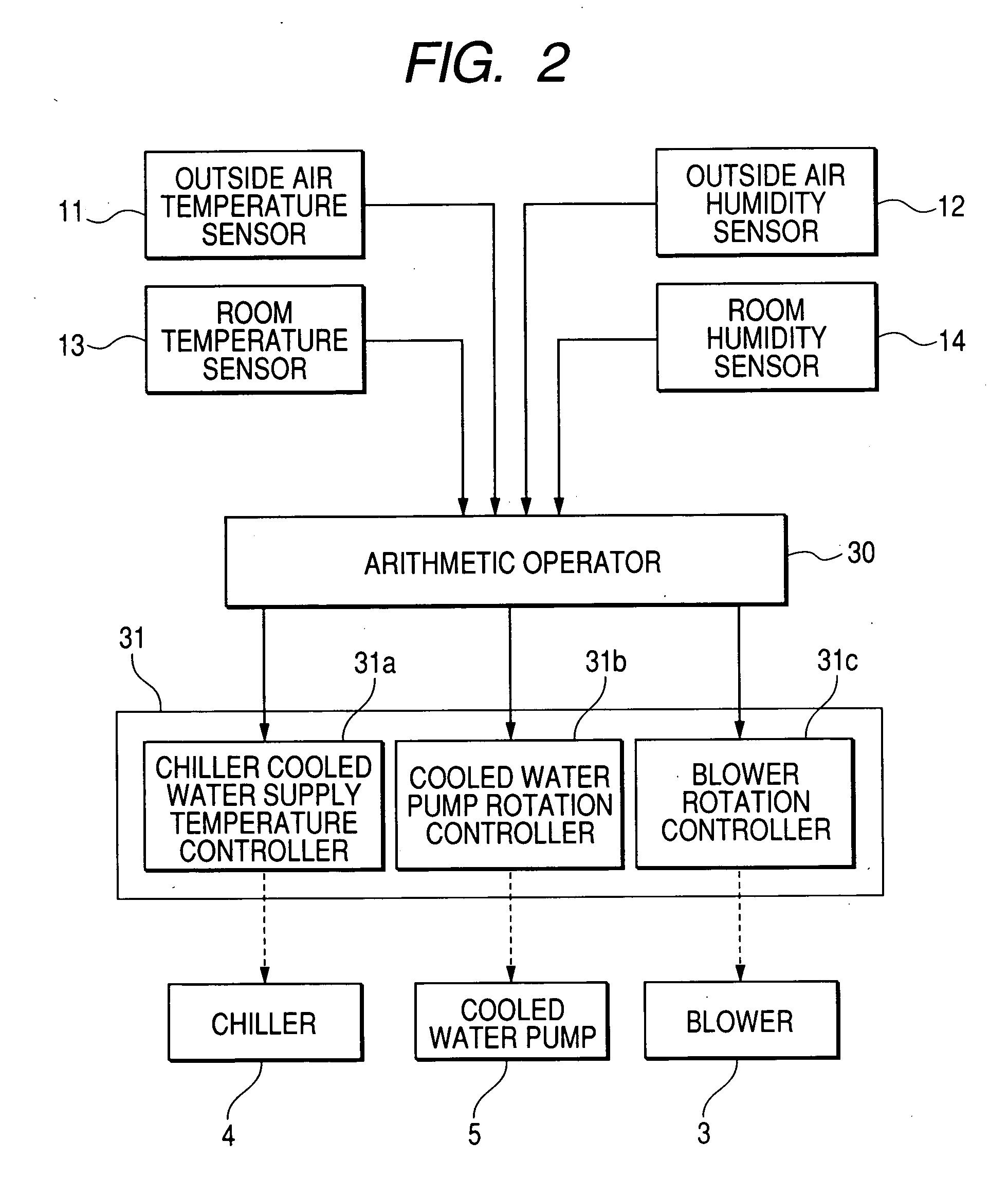
[0070] In the embodiment illustrated in FIG. 9, the difference from the first embodiment of FIG. 1 is that a supply air temperature sensor 15 for measuring the temperature of air at the exit of the air-conditioning unit 1 and a supply air humidity sensor 16 for measuring the humidity of air at the exit of the air-conditioning unit 1 are provided, and the other structure is identical to that of FIG. 1. In the embodiment of FIG. 10, the difference from the first embodiment of FIG. 2 is that the arit...


PUM


Abstract

An air conditioning apparatus comprises an air-conditioning unit including at least a cooling coil as a heat exchanger, a blower, a chiller, and a coolant pump for conducting air-conditioning, wherein the coolant pump pumps the coolant cooled by the chiller to the cooling coil, the cooling coil cools the air through heat exchange of the coolant and the air, the blower supplies the cooled air into a room. Coolant temperature of the chiller, the coolant flow rate of the coolant pump, and the air flow rate of the blower are calculated in accordance with the set points of the indoor temperature and the indoor humidity, and the chiller, coolant pump, and blower are controlled on the basis of the arithmetic calculation results. Thereby, the indoor temperature and indoor humidity are independently controlled in the central air-conditioning system.

Description

CLAIM OF PRIORITY [0001] The present application claims priority from Japanese application serial JP 2005-331031 filed on Nov. 16, 2005, the content of which is hereby incorporated by reference into this application. FIELD OF THE INVENTION [0002] The present invention relates to an air conditioning apparatus and particularly to an air conditioning apparatus that it is possible to control temperature and humidity respectively independently according to sensible heat load and latent heat load. [0003] In air conditioning for industrial use, precision control of temperature and humidity has been conducted from the view point of ensuring quality, for example, in a clean room for manufacturing of semiconductor devices. However, in air conditioning for business offices or home, humidity is often left to chance, although the temperature is controlled in accordance with the set point. [0004] Amenity is strongly influenced by not only temperature but also humidity. For example, under high hum...

Claims


Application Information

Patent Timeline
Patent Type & Authority Applications(United States)
IPC IPC(8): F25D17/04F25D17/02
CPCF24F11/0008F24F11/0009F24F11/0015F24F2011/0013F24F11/30F24F2110/12F24F2110/20F24F11/52F24F11/77F24F11/84F24F11/46F24F11/63
Inventor SASAO, KEIJINAKAJIMA, TADAKATSU
Owner HITACHI LTD
Why Eureka
Try Eureka