Rotating electrical machine

a technology of rotating electrical machines and rotating shafts, which is applied in the direction of rotating parts of magnetic circuits, cooling/ventilation arrangements, magnetic circuit shapes/forms/construction, etc., can solve the problems of large torque and high power required to be produced in a limited space, cooling required in response to increase in loss density, and significantly reducing performance of rotating electrical machines, such as power and efficiency, to achieve the effect of large torque, high power and enhanced cooling performan

Active Publication Date: 2007-03-08
KK TOSHIBA +1
View PDF4 Cites 89 Cited by
  • Summary
  • Abstract
  • Description
  • Claims
  • Application Information

AI Technical Summary

Benefits of technology

[0011] The present invention has been made for the purpose of solving the foregoing problems. An object of the present invention is to provide a rotating electrical machine, whereby a cooling performance is enhanced while securing strength of a rotor, which is large enough for the rotor to withstand high-speed rotation, whereby a large torque and a high power can be obtained while in a compact size, and whereby reliability is enhanced.
[0019] The present invention makes it possible to enhance cooling performance while securing strength of a rotor, which is large enough for the rotor to withstand high-speed rotation, to obtain large torque and high power while in a compact size, and to enhance reliability.

Problems solved by technology

In particular, with regard to rotating electrical machines for cars, such as for hybrid cars, large torque and high power are required to be produced in a limited space.
In this case, large problems are strength of each rotor core against a higher centrifugal force, and a cooling required in response of increase in loss density.
This causes heat demagnetization (irreversible demagnetization), and thus significantly reduces performances of the rotating electrical machine, such as power and efficiency.
For this reason, this raises a serious problem.
However, in response to the high speed, iron loss and harmonic loss increase, and thus the temperature of the rotating electrical machine rises.
In addition, heat of each of the permanent magnets stemming from eddy currents can not be sufficiently cooled down.
As a result, the rotating electrical machine has a problem that the power and efficiency are reduced due to the temperature rise of the rotating electrical machine, and that the reliability is accordingly decreased.
Moreover, in the case of the rotating electrical machine according to Japanese Patent Laid-open Official Gazette No. 2004-343915, the strength of the rotor core against the centrifugal force can not be secured.
This raises a problem that it is difficult for the rotating electrical machine to be operated at a high speed.

Method used


Image

  • Rotating electrical machine
  • Rotating electrical machine
  • Rotating electrical machine

Examples


first embodiment

(First Embodiment)

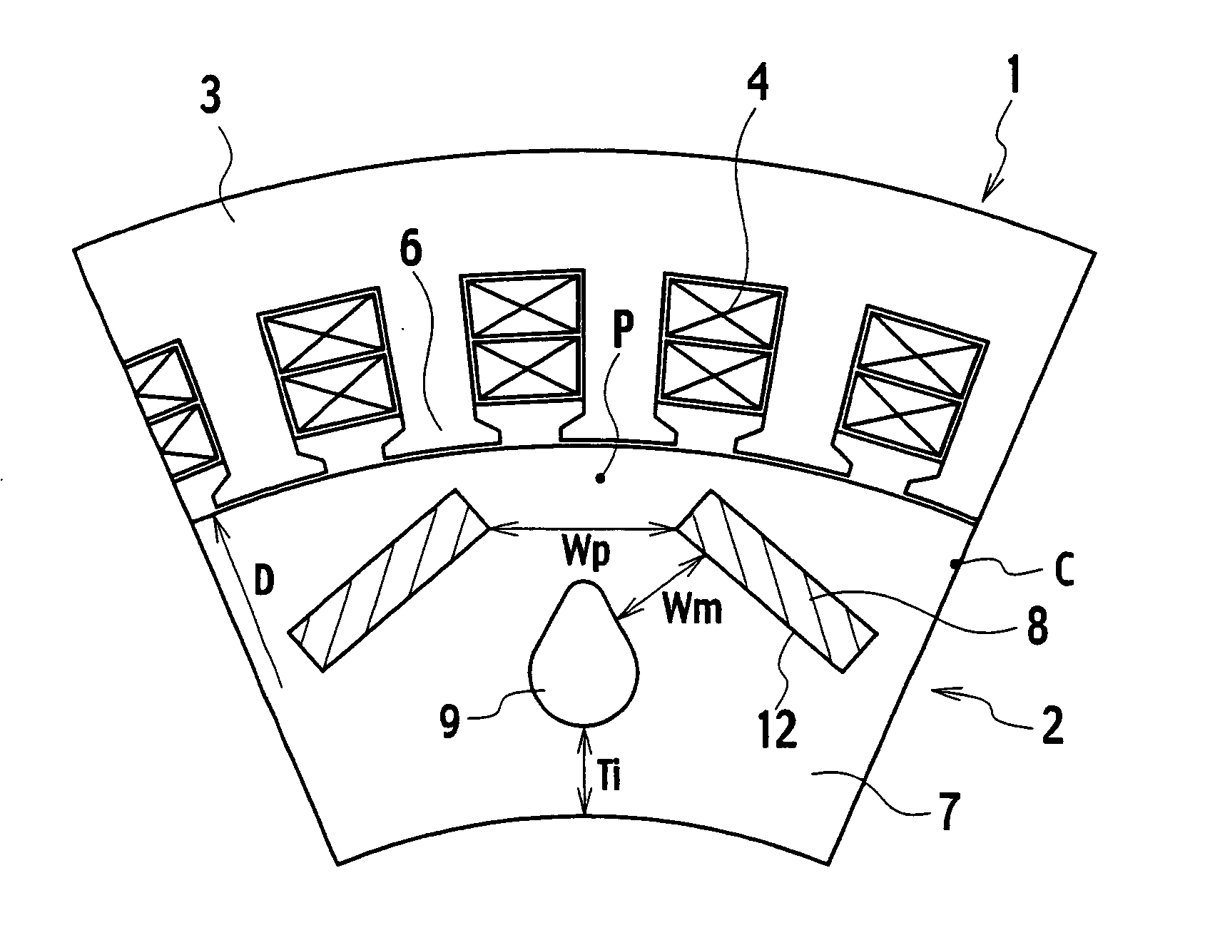
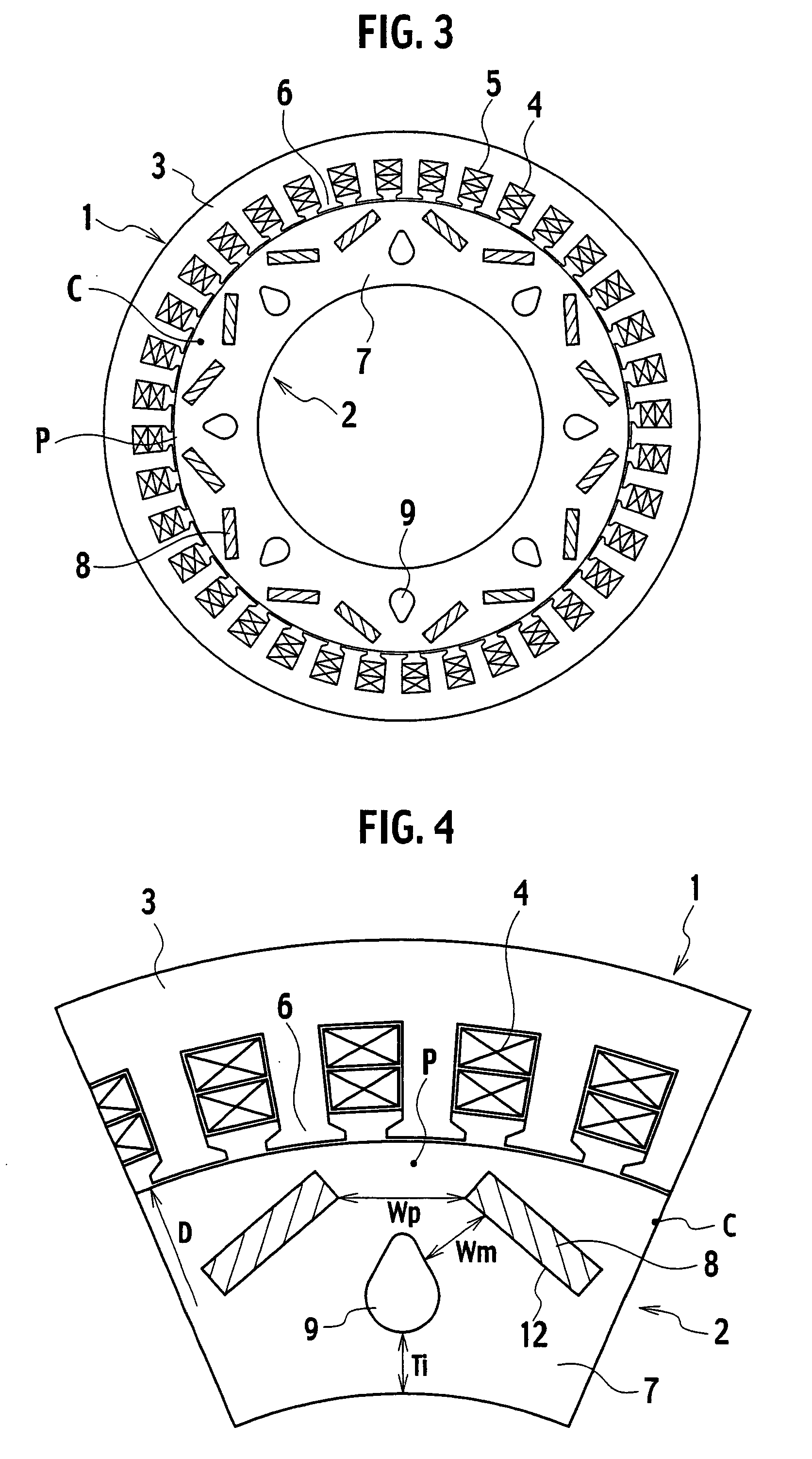
[0032]FIG. 3 is a cross-sectional view of a rotating electrical machine according to a first embodiment of the present invention, which is taken in the radial direction. In FIG. 3, the rotating electrical machine has a stator 1 and a rotor 2 provided to the inside of the stator 1.

[0033] The stator 1 has a stator core 3 constituted by layering a plurality of ring-shaped electromagnetic steel sheets. A plurality of stator slots 5 each for containing an armature winding 4 are formed along the inner circle at intervals in the circumferential direction. A stator tooth 6 facing the rotor 2 is formed between each two of the stator slots 5.

[0034]FIG. 4 is an enlarged view of a part of the rotating electrical machine shown in FIG. 3. The rotor 2 is arranged in the inside of the stator 1 with an interstice interposed between the rotor 2 and each of the stator teeth 6. The rotor 2 includes a ring-shaped rotor core 7 and a plurality of plate-shaped permanent magnets 8 insert...

second embodiment

(Second Embodiment)

[0055]FIG. 7 is a cross-sectional enlarged view of a rotating electrical machine according to a second embodiment of the present invention, which is taken in the radial direction. Incidentally, in the descriptions of the following embodiments, the same reference numerals will be used to designate the same or similar components as those in the previously-described embodiment.

[0056] In the case of this embodiment, each of the permanent magnets 8 is divided into a pair of parts 8a in a direction parallel to the polarization direction in order for the permanent magnet 8 to have an interstice 10 extending in the axial direction of a rotor 2. Concurrently, a duct 11 made of a material with heat conductivity and rigidity is arranged coaxially in the interstice 10 between the divided parts 8a in a way that the duct 11 is in contact with the inner surface of the interstice 10. The inside of the duct 11 is used as a cooling path through which a coolant passes.

[0057] Such ...

third embodiment

(Third Embodiment)

[0060]FIG. 8 is a cross-sectional enlarged view of a rotating electrical machine according to a third embodiment of the present invention, which is taken in the radial direction.

[0061] In the case of this embodiment, each of the permanent magnets 8 is divided into a pair of parts 8a in a direction perpendicular to the polarization direction in order for the permanent magnet 8 to have an interstice 10 extending in the axial direction of a rotor 2. Concurrently, a duct 11 made of a material with heat conductivity is arranged in the interstice 10 between the divided parts 8a in a way that the duct 11 is in contact with the inner surface of the interstice 10. The inside of the duct 11 is used as a cooling path through which a coolant passes.

[0062] Such a configuration makes it possible not only to obtain working effects which are the same as those described with regard to the second embodiment, but also to make the heat transfer area for cooling each of the permanent...


PUM


Abstract

Included are a ring-shaped stator and a ring-shaped rotor arranged inside the stator; the stator includes a stator core with armature windings; the rotor includes a rotor core in which a plurality of permanent magnets are inserted and cooling holes are formed, a coolant flowing in each of the cooling holes; and each of the cooling holes is formed so as to have a sectional view which is a convex toward the outer periphery thereof.

Description

CROSS-REFERENCE TO RELATED APPLICATION [0001] This application is based upon and claims the benefit of priority from the prior Japanese Patent Application No. 2005-259905, filed on Sep. 7, 2005. The entire contents of which are incorporated herein by reference. BACKGROUND OF THE INVENTION [0002] 1. Field of the Invention [0003] The present invention relates to a rotating electrical machine of permanent magnet implanted-type used for hybrid cars and the like. [0004] 2. Description of the Prior Art [0005] Recent years, remarkable research and development of permanent magnets have driven development of permanent magnets each with high magnetic energy product, and to accordingly construction of rotating electrical machines each with higher power in a smaller size. In particular, with regard to rotating electrical machines for cars, such as for hybrid cars, large torque and high power are required to be produced in a limited space. In order to meet this requirement, rotating electrical m...

Claims


Application Information

Patent Timeline
Patent Type & Authority Applications(United States)
IPC IPC(8): H02K1/32H02K1/27
CPCH02K1/32H02K1/2766
Inventor TAKAHASHI, NORIOSAKAI, KAZUTOHASHIDATE, YOSHIOARATA, MASANORIITO, WATARUMATSUBARA, MASAKATSUHANAI, TAKASHIHIRANO, YASUO
Owner KK TOSHIBA
Why Eureka
Try Eureka