Cooling circuit for receiver of solar radiation

a solar radiation and cooling circuit technology, applied in the field can solve the problems of reducing the available contact surface area of solar radiation receivers, and reducing the efficiency of photovoltaic cells, so as to achieve the effect of improving heat transfer, increasing the available contact surface area, and high heat transfer

Inactive Publication Date: 2006-07-18
SOLAR SYST PTY LTD
View PDF26 Cites 86 Cited by
  • Summary
  • Abstract
  • Description
  • Claims
  • Application Information

AI Technical Summary

Benefits of technology

[0043]With the above-described arrangement there is direct thermal contact between the substrate and coolant flowing through the coolant chamber (including the channels) and between the substrate and the side wall and the lands. This construction provides an effective means for transferring heat from the photovoltaic cells via the substrate to the coolant. In particular, the side wall and the lands provide an effective means of increasing the available contact surface area with the coolant to improve heat transfer to the coolant. This is an important feature given the high levels of heat transfer that are required to maintain the photovoltaic cells at temperatures below 80° C., preferably below 60° C., more preferably below 40° C. A further advantage of the construction is that the side wall and the lands enable lateral movement of the substrate and the coolant member—as is required in many situations to accommodate different thermal expansion of the materials that are used in the construction of the modules. Accommodating different thermal expansion of such materials is an important issue in terms of maintaining long term structural integrity of the modules. In this context, it is important to bear in mind that the high levels of heat transfer that are required to maintain the photovoltaic cells at temperatures below 80° C. place considerable constraints on the materials selection for the components of the modules. As a consequence, preferred materials for different components of the modules and for bonding together different components of the modules are materials that have different thermal expansion. There are two aspects to the issue of materials selection and heat transfer. One aspect is the materials requirements of components of the modules, such as the substrate and the coolant member, to define heat flow paths from the photovoltaic cells to coolant flowing through the coolant chamber. The other aspect is the materials requirements for containing the high hydraulic pressures within the coolant chamber that are required to maintain coolant flow through the coolant chamber at required levels. In particular, the second aspect is concerned with materials selection to achieve sufficient bond strength between the substrate and the coolant member.

Problems solved by technology

One significant issue associated with development of commercially viable solar radiation-based electrical power generating systems of the type described above is long term performance of materials and structural integrity of components of the system made from materials as a consequence of:(a) exposure to extremely high intensity solar radiation capable of producing high temperatures, i.e. temperatures considerably above 1000° C.;(b) cycling between high and low intensities of solar radiation; and(c) temperature variations between different parts of structural components.
In addition, the photovoltaic cells are subjected to significant cycling between extremely high and low levels of solar radiation and to variations in solar radiation intensity across the surface of the receiver.
Thus, the receiver addresses the significant issue that a large portion of incident radiation on receivers of large scale solar radiation-based electrical power generating systems is not converted to electricity and manifests itself as heat that reduces the efficiency of photovoltaic cells.
In addition, the modularity of the receiver addresses (at least in part) the issue that optimum locations for large scale solar radiation-based electrical power generating systems tend to be in regions that are remote from major population and manufacturing centres and, therefore, construction of the systems in such remote locations presents significant difficulties in terms of transportation of equipment to the sites, on-site construction, and on-going maintenance (including quick replacement of component parts) at the sites.
Accommodating different thermal expansion of such materials is an important issue in terms of maintaining long term structural integrity of the modules.

Method used


Image

  • Cooling circuit for receiver of solar radiation
  • Cooling circuit for receiver of solar radiation
  • Cooling circuit for receiver of solar radiation

Examples


Embodiment Construction

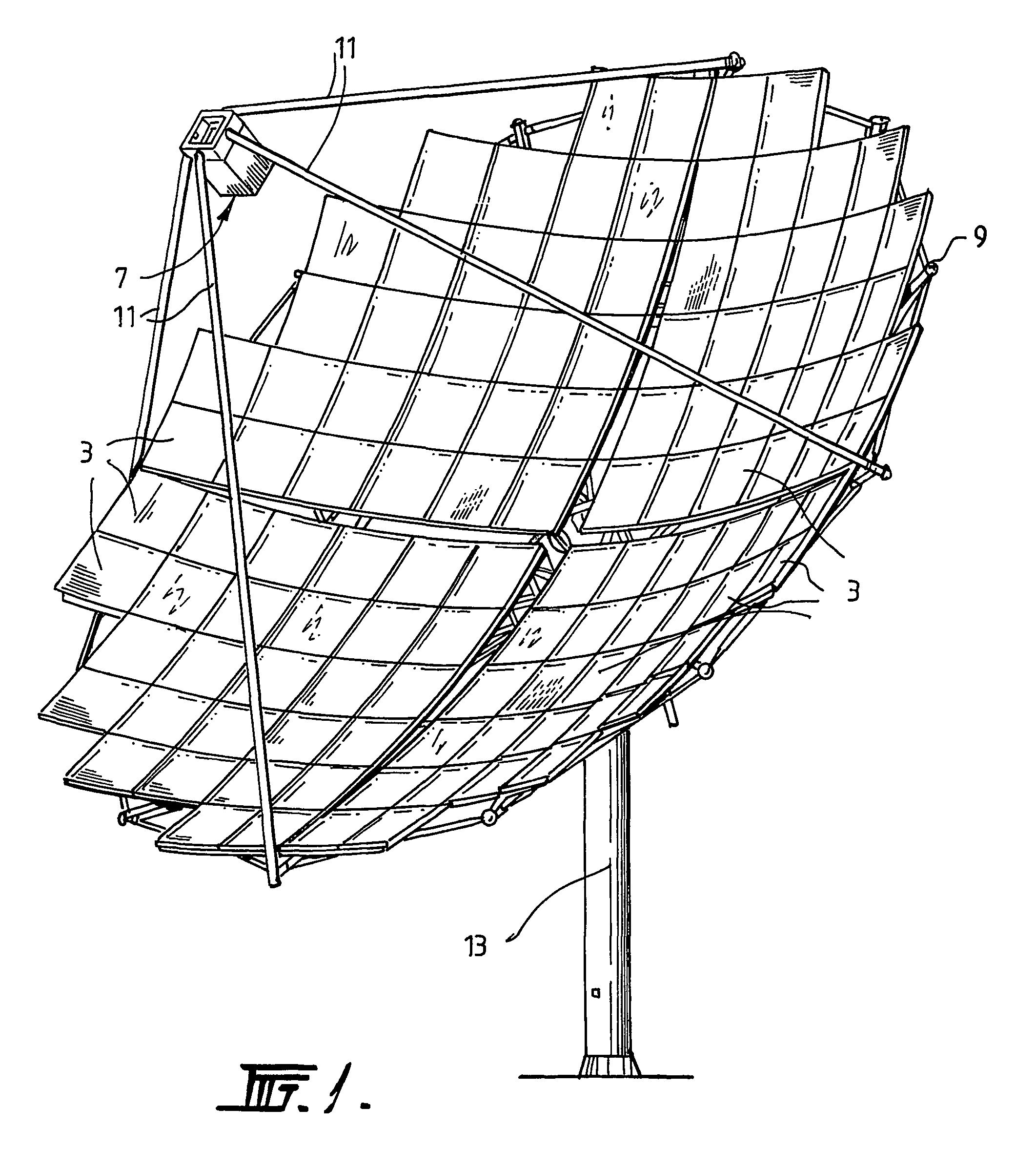
[0072]The solar radiation-based electric power generating system shown in FIG. 1 includes a parabolic array of mirrors 3 that reflects solar radiation that is incident on the mirrors towards a plurality of photovoltaic cells 5.

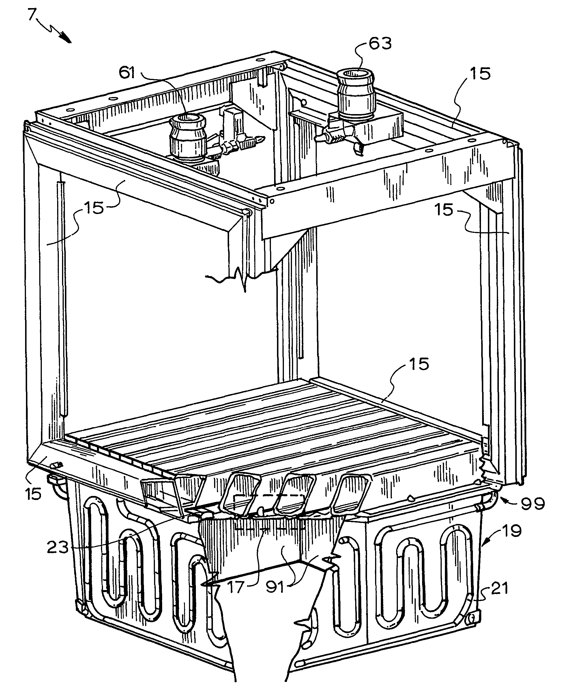
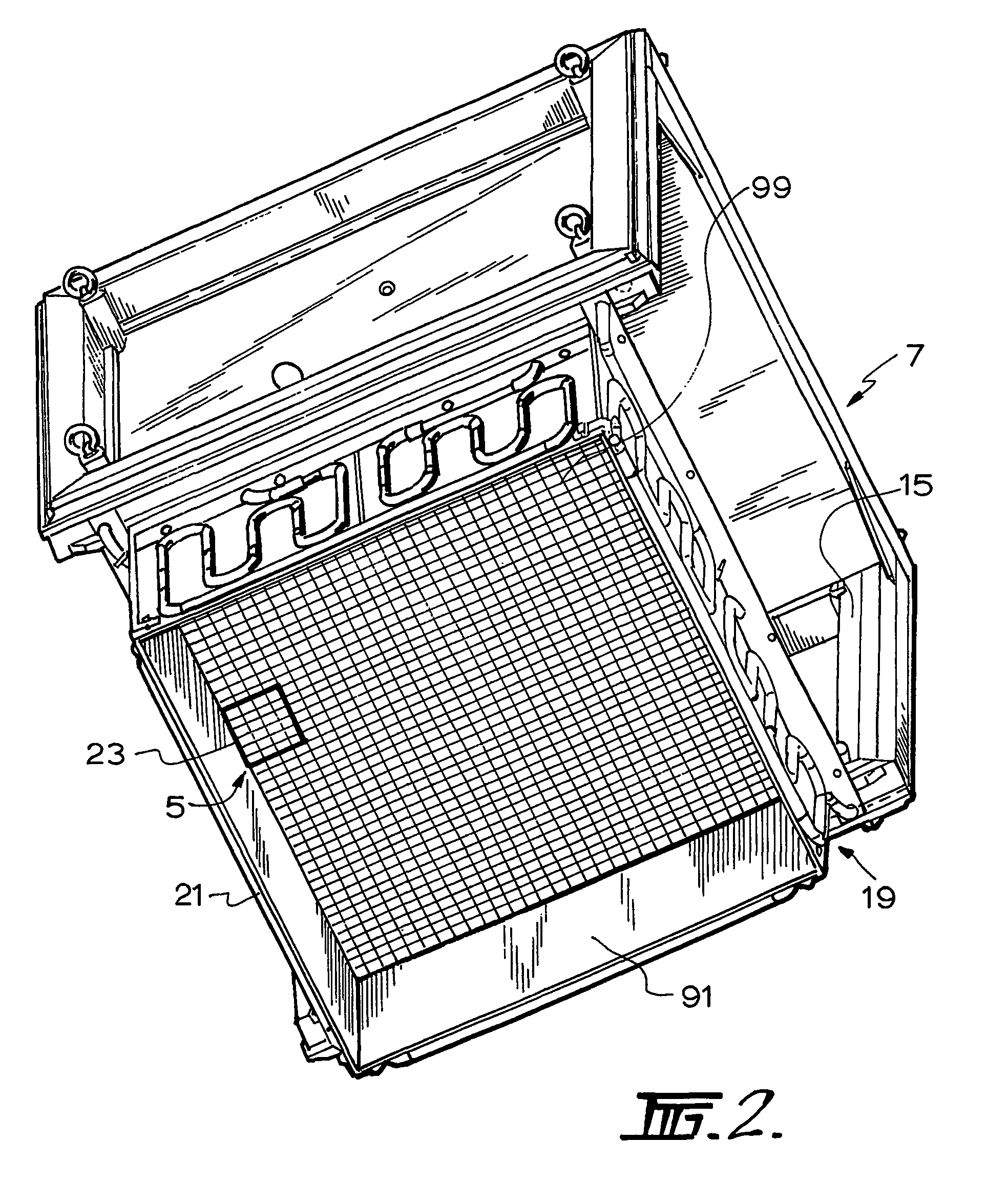
[0073]The cells 5 form part of a solar radiation receiver that is generally identified by the numeral 7.

[0074]As is described in more detail hereinafter, the receiver 7 includes an integrated coolant circuit. The surface area of the mirrors 3 that is exposed to solar radiation is substantially greater than the surface area of the photovoltaic cells 5 that is exposed to reflected solar radiation. The photovoltaic cells 5 convert reflected solar radiation into DC electrical energy. The receiver 7 includes an electrical circuit (not shown) for the electrical energy output of the photovoltaic cells.

[0075]The mirrors 3 are mounted to a framework 9. The mirrors and the framework define a dish reflector.

[0076]A series of arms 11 extend from the framework 9 to the rec...


PUM


Abstract

A receiver for a system for generating electrical power from solar radiation is disclosed. The systems includes the receiver and a means (3) for concentrating solar radiation onto the receiver. The receiver includes a plurality of photovoltaic cell modules. Each module includes a plurality of photovoltaic cells (5), and includes an electrical connection that forms part of the receiver electrical circuit. The receiver includes a coolant circuit for cooling the photovoltaic cells with a coolant. The coolant circuit includes a coolant flow path in each module that is in thermal contact with the photovoltaic cells so that in use coolant flowing through the flow path extracts heat from the photovoltaic cells and thereby cools the cells.

Description

CROSS-REFERENCE TO RELATED APPLICATIONS[0001]This is the National Stage of International Application No. PCT / AU02 / 00402, filed Mar. 28, 2002, and claims the benefit of Australian Patent Application No. PR4038, filed Mar. 28, 2001.FIELD[0002]The present invention relates to a receiver of a system for generating electrical power from solar radiation.BACKGROUND AND SUMMARY[0003]Solar radiation-based electrical power generating systems typically include:[0004](a) a receiver that includes a plurality of photovoltaic cells that convert solar energy into electrical energy and an electrical circuit for transferring the electrical energy output of the photovoltaic cells; and[0005](b) a means for concentrating solar radiation onto the photovoltaic cells of the receiver.[0006]By way of example, the means for concentrating solar radiation may be a dish reflector that includes a parabolic array of mirrors that reflect solar radiation that is incident on a relatively large surface area of the mir...

Claims


Application Information

Patent Timeline
Patent Type & Authority Patents(United States)
IPC IPC(8): F25D23/12H01L25/00H02N6/00F24S20/20F24S23/70H01L31/042H01L31/052H01L31/054H02S20/00
CPCF24J2/07F24J2/10F24J2/4621F24J2/4625H01L31/0547H01L31/052Y02E10/41Y02E10/52H02S20/00H01L31/0521F24S40/50F24S23/70F24S20/20F24S40/55Y02E10/40
Inventor LASICH, JOHN BEAVIS
Owner SOLAR SYST PTY LTD
Why Eureka
Try Eureka