Heated fuel injector

a fuel injector and heated technology, applied in the direction of fuel injectors, machines/engines, mechanical equipment, etc., can solve the problems of increasing the problem of fuel/air charge, difficulty or inability to start spark-ignited engines fueled by ethanol, and increasing the difficulty or inability to start spark-ignited engines. , to achieve the effect of increasing the thermal efficiency of the heated fuel injector, increasing the available contact surface area, and large surface area

Inactive Publication Date: 2009-12-03
DELPHI TECH INC
View PDF5 Cites 36 Cited by
  • Summary
  • Abstract
  • Description
  • Claims
  • Application Information

AI Technical Summary

Benefits of technology

[0011]Briefly described, the thermal efficiency of a heated fuel injector is increased separately or in combination by directing the fuel flow along an inner circumferential contour of a heated injector body, by limiting the volume of fluid bypassing the heated inner surface of the injector body, by redirecting heat from the heated injector body to typically unheated portions of the fuel flow field within the fuel passage of the injector body, and by increasing the available contact surface area for heat transfer. Improved heat transfer from the heated injector body to the fuel flowing through the injector body is realized by integrating surface enlarging features into the inside surface of an injector body or by positioning an insulating spacer or a thermally conductive spacer within the fuel passage of the heated injector body. The thermally insulating spacer functions as a flow diverter and may be combined with an enlarged contact surface area and / or a plug that prevents fuel from flowing through a hollow pintle shaft. The thermally conductive internal spacer functions as a heat exchanger, has a relatively large surface area in contact with fuel flowing through the fuel injector, a relatively small mass, and maintains a tight fit with the internal surface of the heated fuel injector body for optimal heat transfer, which enables the heat to be readily transferred to the thermally conductive spacer.

Problems solved by technology

However, in a spark-ignited engine fueled by alcohols such as ethanol, or mixtures of ethanol and gasoline having a much higher flash point, ignition of the fuel / air charge may not occur at all under cooler climate conditions.
For example, ethanol has a flashpoint of about 12.8° C. Thus, starting a spark-ignited engine fueled by ethanol can be difficult or impossible under cold ambient temperature conditions experienced seasonally in many parts of the world.
The problem is further exacerbated by the presence of water in such mixtures, as ethanol typically distills as a 95 / 5% ethanol / water azeotrope.
The use of such auxiliary system adds cost to the vehicle and to the operation of the vehicle and may increase the maintenance required for the engine.
However, if the surface area of the heater is increased by increasing its diameter, the outside surface of the injector body needs to be increased too, which leads to an increased overall mass of the body.
Notwithstanding the weight and size penalty associated therewith, if the overall mass of the body is increased, then the initial time delay to heat the fuel will also increase because the mass of the body has to be heated before its surface will heat the fuel.
Also, since a larger diameter fuel injector body causes an increased internal fluid volume, and the fuel itself is a relatively poor heat conductor, the larger volume of fluid does not transfer the heat well from the fluid near the heater surface area to the rest of the fluid.
Stainless steel is known to be a poor heat conductor and, even when using a relatively thin injector body, most of the energy delivered by the heater is transferred to the external plastic overmold.
Since the heat diffusivity of ethanol is very low, on the order of about 27 times below the one of stainless steel, this condition is worsened with the use of ethanol fuels.

Method used


Image

  • Heated fuel injector
  • Heated fuel injector
  • Heated fuel injector

Examples


first embodiment

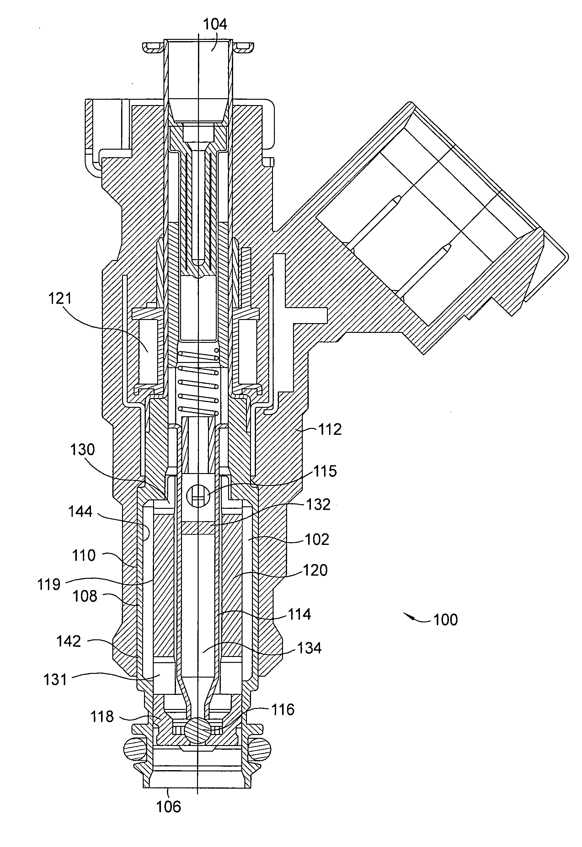
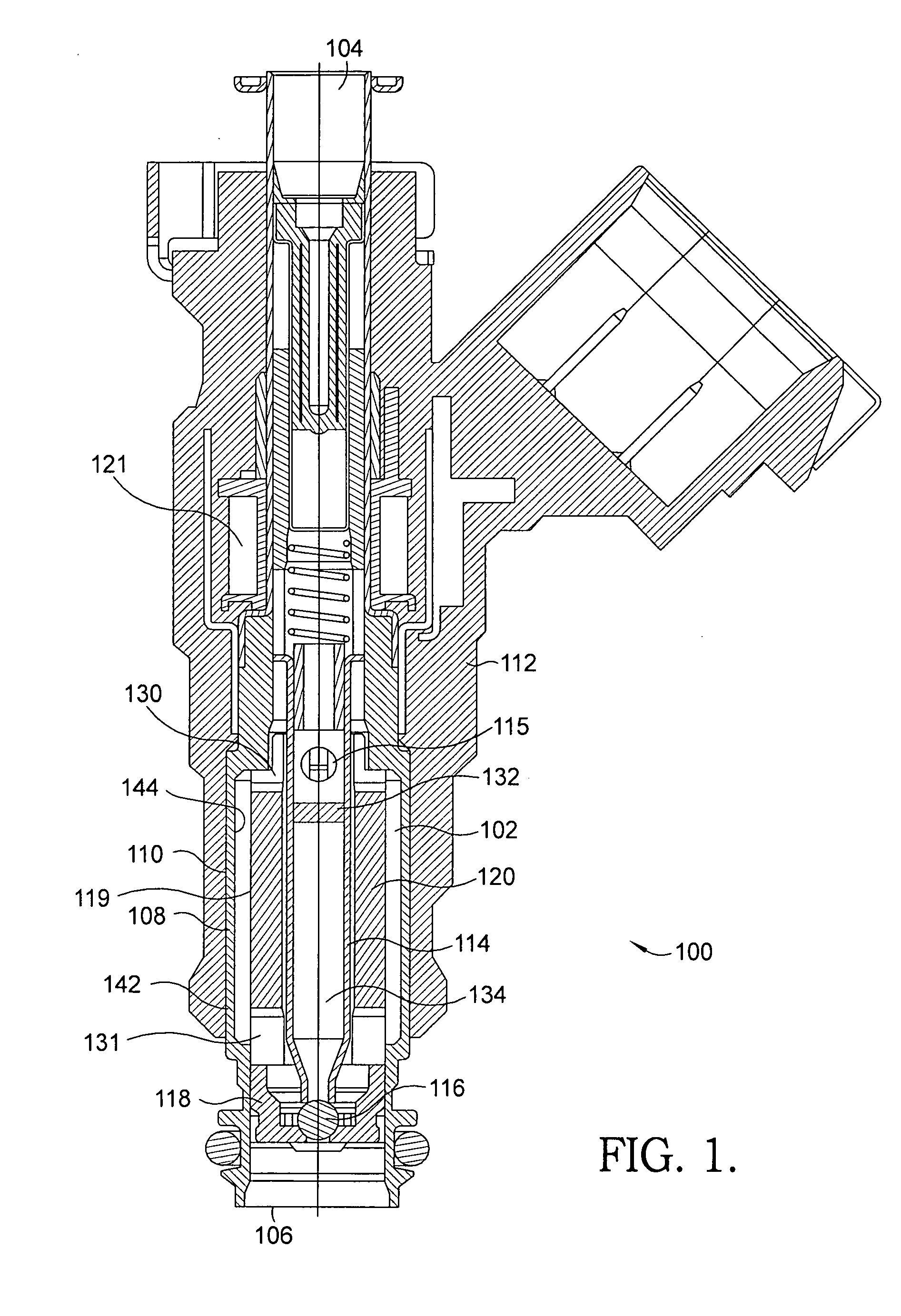
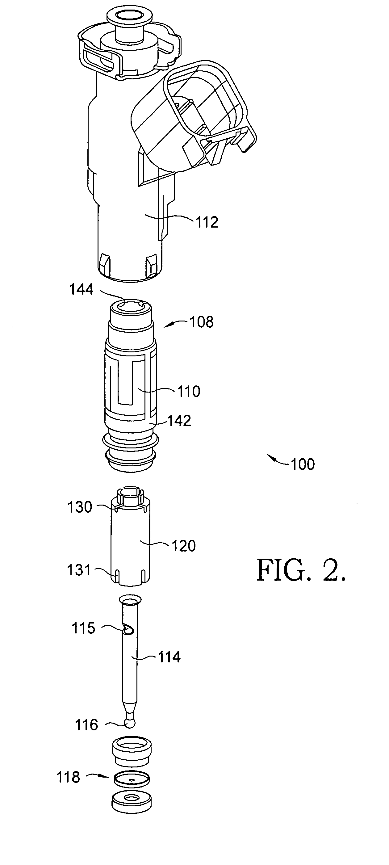
[0035]Referring to FIGS. 1 and 2, a fuel injector 100 includes a spacer 120 having a low thermal conductivity, assembled within a body 108 of injector 100 in accordance with the invention. Injector 100 may be a fuel injector for port injection as illustrated or a fuel injector for direct injection of fuel. The fuel flowing through fuel injector 100 from a fuel inlet 104 to a fuel outlet 106 may be any type of liquid fuel, for example, an ethanol based fuel, gasoline, or diesel.

[0036]Body 108 of fuel injector 100 has a heater element 110 applied to an outside surface 142 of the body for transferring heat to the body by the heater element. Heater element 110 may be, for example, a thick film heater printed on the outside surface 142 of body 108. An overmold 112 or other type of protection covers body 108 and heater element 110. Fuel passage 102 is defined by an inside surface 144 of body 108 and an outside surface 119 of spacer 120. A valve assembly includes pintle shaft 114 and a val...

second embodiment

[0041]Referring to FIGS. 4 (A and B) through 6 (A and B), exemplary fuel injectors 200, 300 and 400, and fuel injector bodies 208, 308 and 408, including features such as single threads 246, multiple helical threads 346 and an array of projecting pins 546 are shown. These features provide an increased heated surface area coming in contact with fuel in accordance with the invention. By increasing the inner surface area of the heated injector body, the efficiency of heat transfer from the heated body to a fuel having a low heat diffusivity, such as ethanol based fuels, may be increased.

[0042]Referring to FIGS. 4A and 4B, a fuel injector 200 including a body 208 having an outside surface 142 and an inside surface 244 is shown. (Note: features identical with those in fuel injector 100 carry the same numbers; features analogous but not identical carry the same numbers but in the 200 series.) A single groove formed as a helical channel 246 is included on inside surface 244 of body 208. He...

third embodiment

[0048]Referring to FIGS. 7 through 11, spacers 620, 720, and 820 are assembled within a heated body of a fuel injector, such as body 608 of fuel injector 600 as shown in FIG. 8 in accordance with the invention. Thermally conductive spacers 620, 720, and 820 are in direct thermal contact with the heated body (see, for example, contact points 749 of feature 748 with body 708 in FIG. 9), and are utilized as heat exchangers conducting heat to the fuel as well. By adapting thermally conductive spacers 620, 720, and 820 to be in direct thermal contact with the heated body, the available surface area for heat transfer to the fuel can be substantially increased and heat energy can be redirected to otherwise unheated portions of the flow field of the fuel injector. As a result, the thermal efficiency of the heated fuel injector can be improved.

[0049]Spacers 620, 720, and 820 may be formed of a material different from the material of the heated body. This allows greater latitude for selecting...


PUM


Abstract

A heated fuel injector includes a heated body, liquid fuel flowing through a fuel passage within the body, and a member that increases heat transfer from the heated body to the fuel within the fuel passage. The thermal efficiency of the fuel injector is increased separately or in combination by diverting the fuel flow along an inner circumferential contour of the heated body, by limiting the volume of fuel bypassing the heated inner surface of the body, by redirecting heat from the body to unheated portions of the fuel flow field within the fuel passage, and by increasing the available contact surface area for heat transfer. Improved heat transfer from the heated body to the fuel is achieved by integrating features that increase the contact surface area into the inside surface of the body or by positioning an insulating or a thermally conductive spacer within the fuel passage.

Description

TECHNICAL FIELD[0001]The present invention relates to internal combustion engines; more particularly, to means for vaporizing liquid fuels; and most particularly, to an apparatus and method for effectively and evenly heating fuel within a fuel injector for consumption by the engine.BACKGROUND OF THE INVENTION[0002]Fuel-injected internal combustion engines fueled by liquid fuels, such as gasoline, diesel, and by alcohols, in part or in whole, such as ethanol, methanol, and the like, are well known. Internal combustion engines typically produce power by controllably combusting a compressed fuel / air mixture in a combustion cylinder. For spark-ignited engines, both fuel and air first enter the cylinder where an ignition source, such as a spark plug, ignites the fuel / air charge, typically just before the piston in the cylinder reaches top-dead-center of its compression stroke. In a spark-ignited engine fueled by gasoline, ignition of the fuel / air charge readily occurs except at extremely...

Claims


Application Information

Patent Timeline
Patent Type & Authority Applications(United States)
IPC IPC(8): B05B1/24
CPCF02M53/06F02M51/061
Inventor TRAPASSO, DAVID J.WILLIAMS, ARTHUR R.HOYER, KEVIN S.SUGIARTO, TANTOBREED, MICHAEL A.GRAMMAR, ADRIAN G.MCCLAIN, KEITH E.SHORT, JASON C.VOLPATO, ORLANDOFELICE, LUCIANO
Owner DELPHI TECH INC
Why Eureka
Try Eureka