Heat pump hot-water supply system

a technology of hot water supply system and heat pump, which is applied in the direction of domestic hot water supply system, heating type, instruments, etc., can solve the problems of large heat loss, large energy consumption, and difference between hot water temperature and outside air temperature, and achieves good energy efficiency, small mass, and narrow mounting space

Inactive Publication Date: 2005-04-05
HITACHI APPLIANCES INC
View PDF17 Cites 34 Cited by
  • Summary
  • Abstract
  • Description
  • Claims
  • Application Information

AI Technical Summary

Benefits of technology

The first object of this invention is to provide a hot-water supply system which needs a narrow mounting space, and has a small mass and a good energy efficiency.
The second object of this invention is to provide a hot-water supply system which can decrease the length of time for the stabilization of hot-water temperature when the hot water is supplied from the hot-water supply system which needs a narrow mounting space and has a small mass.
The third object of this invention is to provide a hot-water supply system which needs a narrow mounting space and has a small mass, and allows additional heating of the bath water.

Problems solved by technology

Furthermore, a great deal of energy is required to heat up a large quantity of hot water.
In addition, storing water at high temperatures results in a substantial difference between the hot water temperature and the outside air temperature and therefore in a big heat loss by heat dissipation, consequently requiring the use of an excess energy.
The heat pump hot-water supply system, therefore, can not be installed in such a narrow space or a low-strength place as the balcony of an apartment house or a condominium.
According to this unit, however, the hot water in the hot-water storage tank is sometimes used up; in such a case, water can not be heated instantly, resulting in hot water starvation.
Furthermore, heat is dissipated out from the surface of the hot-water storage tank which stores a large quantity of hot water of higher temperatures than the outside air temperature, resulting in waste of energy and a drop of temperatures.

Method used


Image

  • Heat pump hot-water supply system
  • Heat pump hot-water supply system
  • Heat pump hot-water supply system

Examples


Embodiment Construction

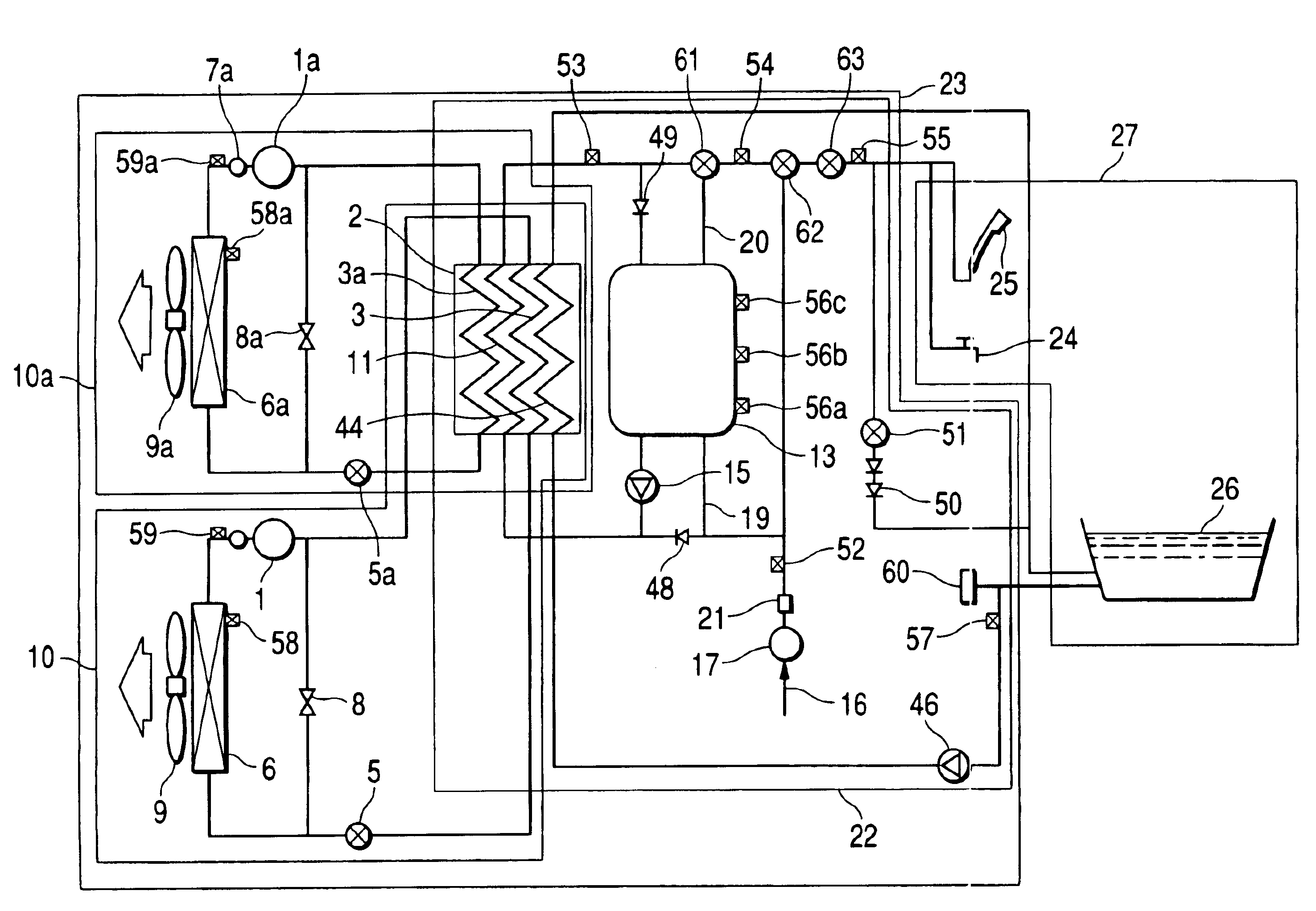
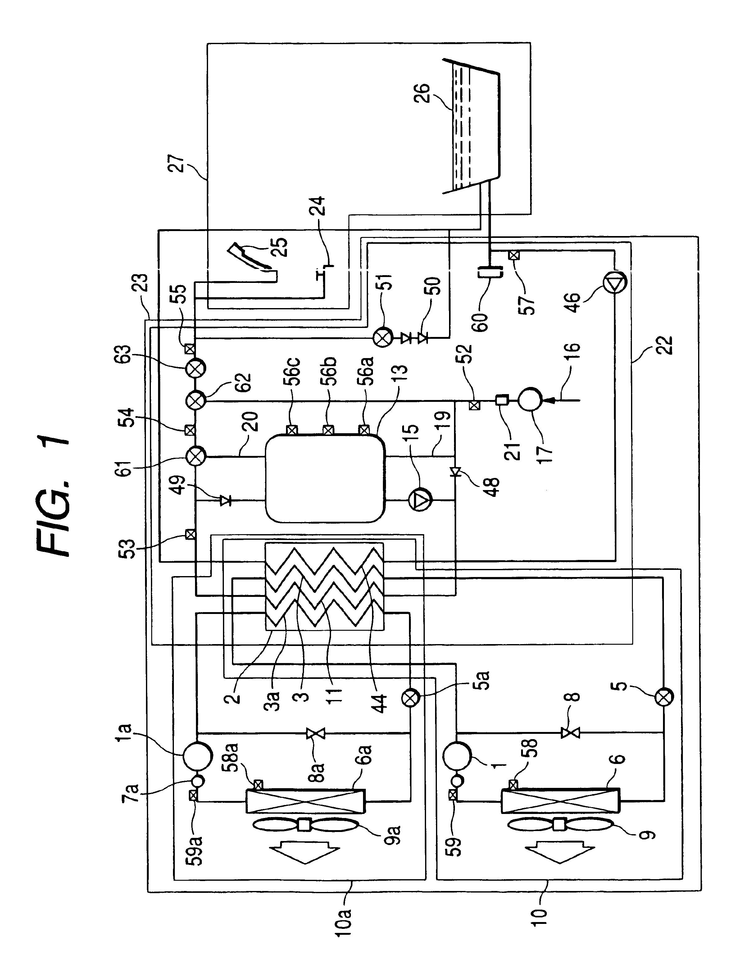
An example of a heat pump hot-water supply system tank will be explained with reference to the accompanying drawings. FIG. 1 shows one example of the heat pump hot-water supply system according to this invention.

First, a refrigeration cycle will be described. The refrigeration cycle includes two heat pump circuits: one is a heat pump circuit 10 in which equipment constituting the refrigeration cycle are connected by a refrigeration pipe, through which the equipment are filled with the refrigerant and hermetically sealed, and the other is a heat pump circuit 10a added to realize a maximum capacity necessary for supplying hot water. In the present example, two heat pump circuits are adopted to constitute the hot-water supply system. In this case, either one circuit or three or more circuits may be used in accordance with the performance of the compressor and the heat exchanger and the hot-water supplying capacity.

The refrigerant (CO2) compressed by compressors 1 and 1a flows into a he...


PUM


Abstract

A hot-water supply system heats water through heat exchange between high-temperature refrigerant of a heat pump circuit and water of a water circulating circuit. The system is an instantaneous water heater unit for instantaneously heating, at a water heat exchanger, water supplied through a water supply pipe and supplying hot water to a using end unit. Therefore, a large-capacity hot-water storage tank is not needed. Sufficient heat of condensation to heat water can not be produced, because pressure conditions of the heat pump circuit is not stabilized just after the start of operation. Therefore, during a short period of rising time, hot water stored in a hot-water supply tank and water from the water heat exchanger are mixed and the mixture is supplied to keep the hot water at a preset temperature. Therefore, it is possible to use a smaller hot-water supply tank.

Description

FIELD OF THE INVENTIONThis invention relates to a hot-water supply system utilizing a heat pump circuit.BACKGROUND OF THE INVENTIONAs conventional hot-water supply systems, there have been adopted a combustion-type hot-water supply system and an electric water heating system. The combustion-type hot-water supply system has no hot-water storage tank. In this unit, a gas is burned to instantly heat up water with its high combustion heat to supply hot water. On the other hand, the electric water heating system has a large-capacity hot-water storage tank, in which a large quantity of water heated during the nighttime with an electric water heater by utilizing a low-cost midnight power is held, so that the hot water held in the hot-water storage tank may be used during the daytime.Recently, however, a heat pump hot-water supply system having a 300 to 500 percent higher energy efficiency than the electric water heating system has come into widespread use. The heat pump hot-water supply sy...

Claims


Application Information

Patent Timeline
Patent Type & Authority Patents(United States)
IPC IPC(8): F24D17/02F25B9/00F25B30/02F25B30/00F24H1/00
CPCF24D17/02F25B9/008F25B30/02F25B2309/061Y02B30/741F25B2400/0403F25B2400/0411F25B2400/06F25B2600/021F25B2339/047Y02B30/70
Inventor SAITOH, KENICHIGOMMORI, MASAHIKOKOGURE, HIROSHIASHIDA, HARUKOOZAWA, TAKEOOKAMURA, TETSUNOBU
Owner HITACHI APPLIANCES INC
Why Eureka
Try Eureka