Turbine with fluidically-controlled valve and swirler with a bleed hole

a fluid control valve and swirler technology, applied in the field of swirlers, can solve the problems of reducing the reliability of the valve and adding costs, and achieve the effect of reducing the air flow

Inactive Publication Date: 2010-01-21
SIEMENS AG
View PDF7 Cites 34 Cited by
  • Summary
  • Abstract
  • Description
  • Claims
  • Application Information

AI Technical Summary

Benefits of technology

[0018]According to a second aspect, an inventive combustor comprises a combustion chamber, a flow channel surrounding the outer wall of the combustion chamber and being in flow communication with the combustion chamber and with a burner plenum. An inventive f

Problems solved by technology

However, those servo-controlled valves comprise moving parts which require servo

Method used


Image

  • Turbine with fluidically-controlled valve and swirler with a bleed hole
  • Turbine with fluidically-controlled valve and swirler with a bleed hole
  • Turbine with fluidically-controlled valve and swirler with a bleed hole

Examples


Embodiment Construction

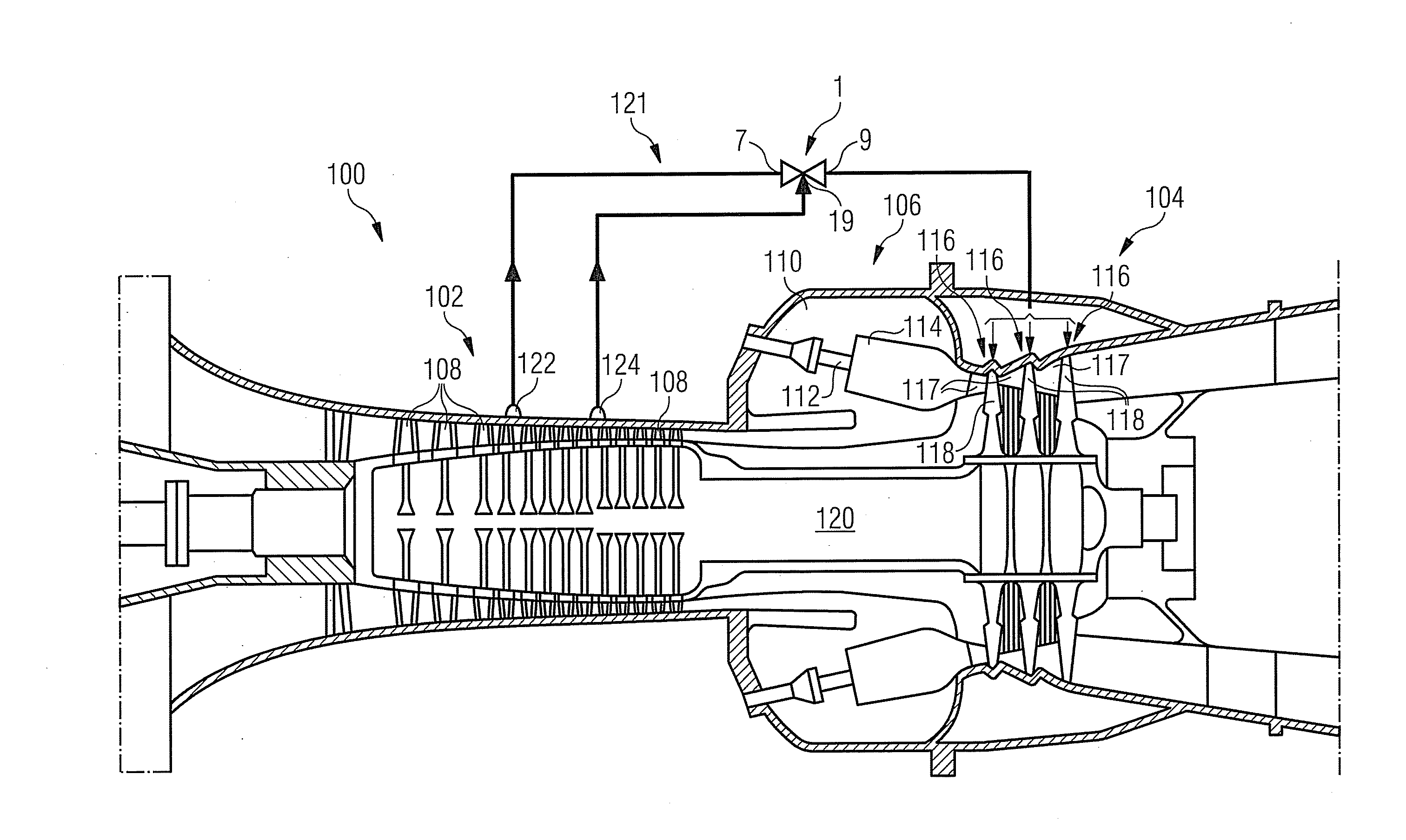
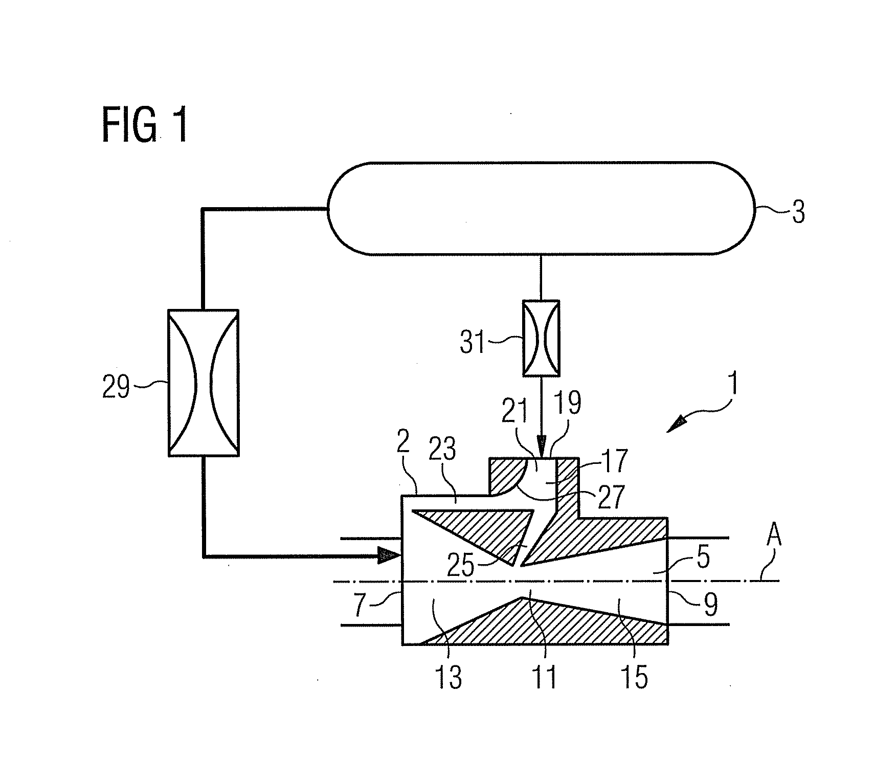
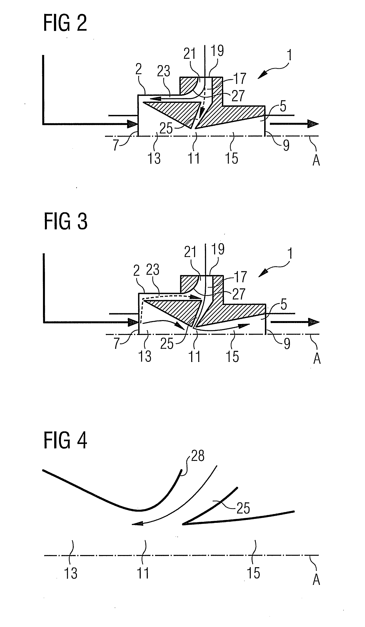
[0031]The inventive valve and its function will be described with reference to FIGS. 1 to 3. FIG. 1 also shows an option of connecting the inventive valve 1 to a pressure reservoir 3.

[0032]The valve 1 comprises a valve housing 2, a main flow channel 5 with a main flow entrance 7, a flow exit 9, and a constricted channel region 11. The constricted channel region 11 is formed by an upstream channel section 13 which follows the main flow entrance 7 and shows a reducing cross section, and a downstream flow section 15 which follows the upstream flow section 13 and shows an expanding cross section towards the flow exit 9, so that the main flow channel 5 adopts the form of a venturi nozzle.

[0033]The valve 1 further comprises a control flow channel 17 with a fluid jet forming control entrance 19, a common channel section 21 following the control entrance 19, a first branch channel 23 emerging from the common channel section 21 and leading to the main flow entrance 7 of the main flow channel...


PUM


Abstract

A fluidically-controlled valve is provided. The fluidically-controlled valve includes a main flow channel with a main flow entrance, a flow exit and a constricted channel section located between the main flow entrance and the flow exit. The fluidically-controlled valve also includes a control flow channel including a jet forming control entrance, a first branch channel, a second branch channel, a common channel section, and a convex channel wall. The common channel section follows the control entrance, the first branch channel emerges from the common channel section and leads to the main flow entrance, the second branch channel emerges from the common channel section and leads to the constricted channel section, and the convex channel wall extends from the common channel section into the first branch channel. The fluidically-controlled valve can be used in bypasses present in turbines or in swirlers of gas turbine combustors.

Description

CROSS REFERENCE TO RELATED APPLICATIONS[0001]This application claims priority of European Patent Office application No. 08012847.3 EP filed Jul. 16, 2008, which is incorporated by reference herein in its entirety.FIELD OF INVENTION[0002]The present invention relates to a fluidically-controlled valve and to a turbine, in particular a gas turbine, with a bypass in which a valve is present. In addition, the invention relates to a swirler, in particular a gas turbine swirler, with a bleed hole.BACKGROUND OF INVENTION[0003]Bypasses are, for example, used in gas turbines to bleed compressor air away from the burners of the gas turbine or from the compressor to the turbine section, in particular for active clearance control. To control the air flow from the burners or to the turbine section, respectively, control valves are present in the bypasses. A gas turbine with bypasses used for active clearance control is, for example, disclosed in SE 9801821-1.[0004]Up to now typically servo-contro...

Claims


Application Information

Patent Timeline
IPC IPC(8): F02C9/18F15C1/08
CPCF01D17/105F01D19/02F02C6/08F05D2260/601F23R3/14F23R3/26F05D2270/173Y10T137/206
Inventor SENIOR, PETER
Owner SIEMENS AG
Why Eureka
Try Eureka