Turbocharger

a turbocharger and internal combustion engine technology, applied in the direction of combustion engines, internal combustion piston engines, machines/engines, etc., can solve the problems of limited inlet pressure of si engines, major difficulties that must be overcome, and advanced si engine turbocharging and other problems, to achieve the effect of reducing cost and fast catalyst light-o

Inactive Publication Date: 2005-06-16
FORD GLOBAL TECH LLC
View PDF16 Cites 33 Cited by
  • Summary
  • Abstract
  • Description
  • Claims
  • Application Information

AI Technical Summary

Benefits of technology

[0021] 3. The load bearing portion (the outer shell) is less subject to heat loads, and can hence be manufactured from a more cost-efficient metal or alloy.
[0022] Further, it is advantageous that the “efficient mass”, i.e. the mass that must be heated prior to catalyst light-off, is significantly reduced, since a smaller mass to be heated allows for a faster catalyst light-off.
[0023] The jacketed integrated turbocharger / manifold according to an embodiment of the present invention also allows for a cost reduction compared to an ordinary, die cast, single component, high temperature manifold / turbocharger assembly. Furthermore, joining problems of the single components can be avoided, which significantly reduces the risk of leakage of exhaust gases prior to the catalyst.

Problems solved by technology

Turbocharging has a number of advantages over so called naturally aspirated (NA) engines, i.e. non-turbocharged or compressor-fed engines, but there are also some major difficulties that must be overcome, especially for turbocharged gasoline engines.
Turbocharging of SI engines is far more advanced and complicated; as is well known to persons skilled in the art of combustion engines, the inlet pressure of SI engines is limited by occurrence of knock, i.e. charge detonation, in the engine cylinders during combustion.
Further, SI engines rarely use excess air during combustion, which leads to higher exhaust gas temperatures.
Today, most engine manufacturers have a 980 C. temperature limit of the exhaust gases, since the exhaust manifold and the turbocharger are not capable of handling higher temperatures.
Except from constituting a strength problem, hot parts are a problem affecting the environment in the engine compartment due to heat radiation.
Both a low compression ratio and a delayed spark advance do however further increase the exhaust temperature, which rapidly will exceed the predetermined levels.
Of these two options, the latter is the most common, since an air diluted combustion gets very unstable and produces large amounts of unburned hydrocarbons, which will react with the oxygen in a downstream catalyst and ruin it.
One large drawback with using cast metal for such components is that they get heavy (a cast metal manifold and turbo system for a 5-cylinder 2.5 litre engine weighs approximately 11-16 kg).
To this should be added the problems occurring when assembling two components subject to high temperatures.
One further problem with die cast metal or alloy occurs if a higher temperature capability is desired; cast alloys capable of standing high temperatures tend to crack and are very expensive.
The high weight (or mass) of a prior art manifold / turbocharger assembly is even more detrimental when the demands for a catalyst is considered; due to reasons of catalyst endurance, the catalyst is almost always located downstream the turbocharger.
A large mass upstream the catalyst gives problems when it comes to catalyst light-off; before the catalyst lights off, it is necessary to heat all components upstream the catalyst above the catalyst light-off temperature.
These alloys are very expensive, and difficult to cast.
As can be understood, this is a very large cost increase for a mass-produced product like a car.
As mentioned earlier, heat radiation from hot components constitute a major problem in the engine compartment, e.g. since fuel hoses and sensitive equipment is placed there.
Furthermore, the efficiency of the turbocharger is negatively affected by the fact that heat is lost from the exhaust manifold.

Method used


Image

  • Turbocharger
  • Turbocharger
  • Turbocharger

Examples


Embodiment Construction

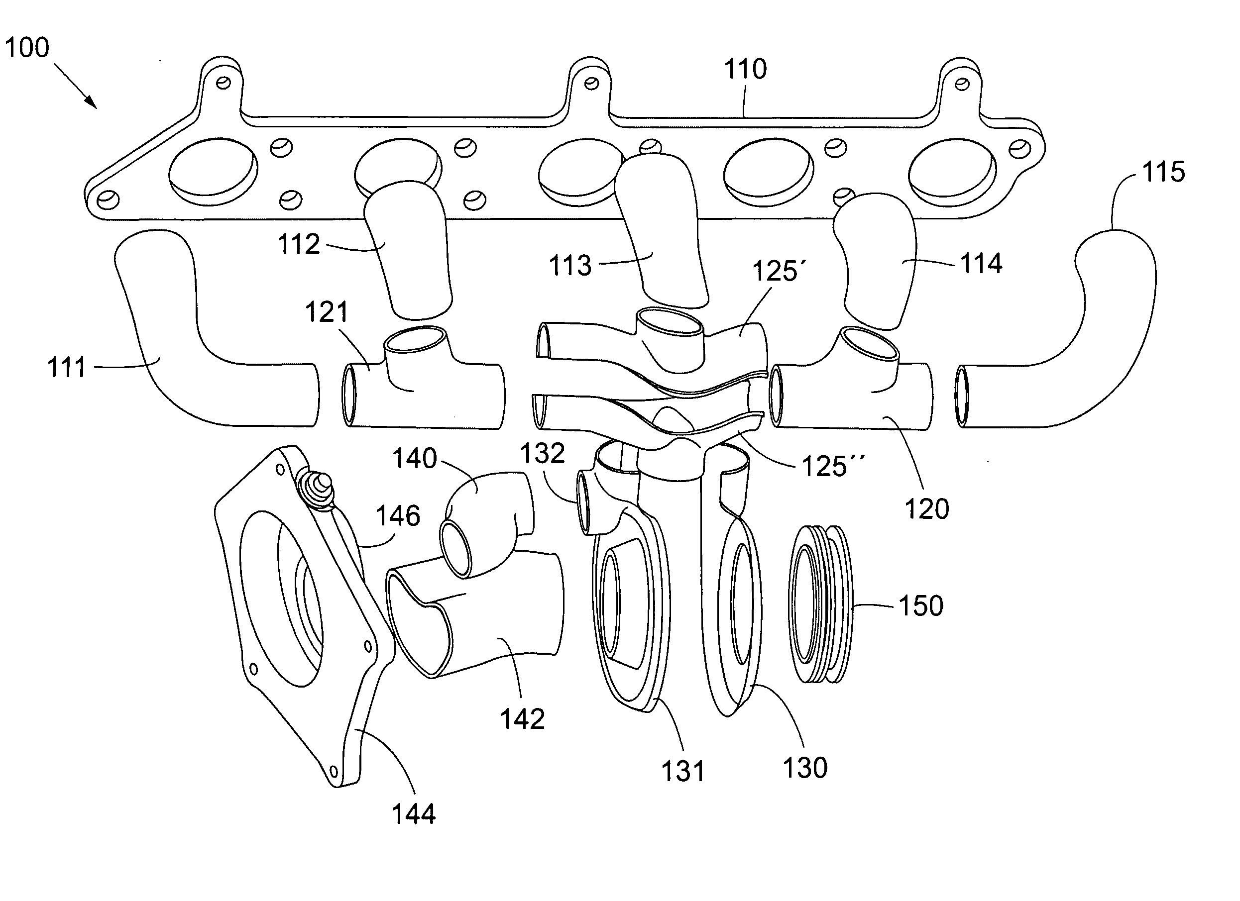
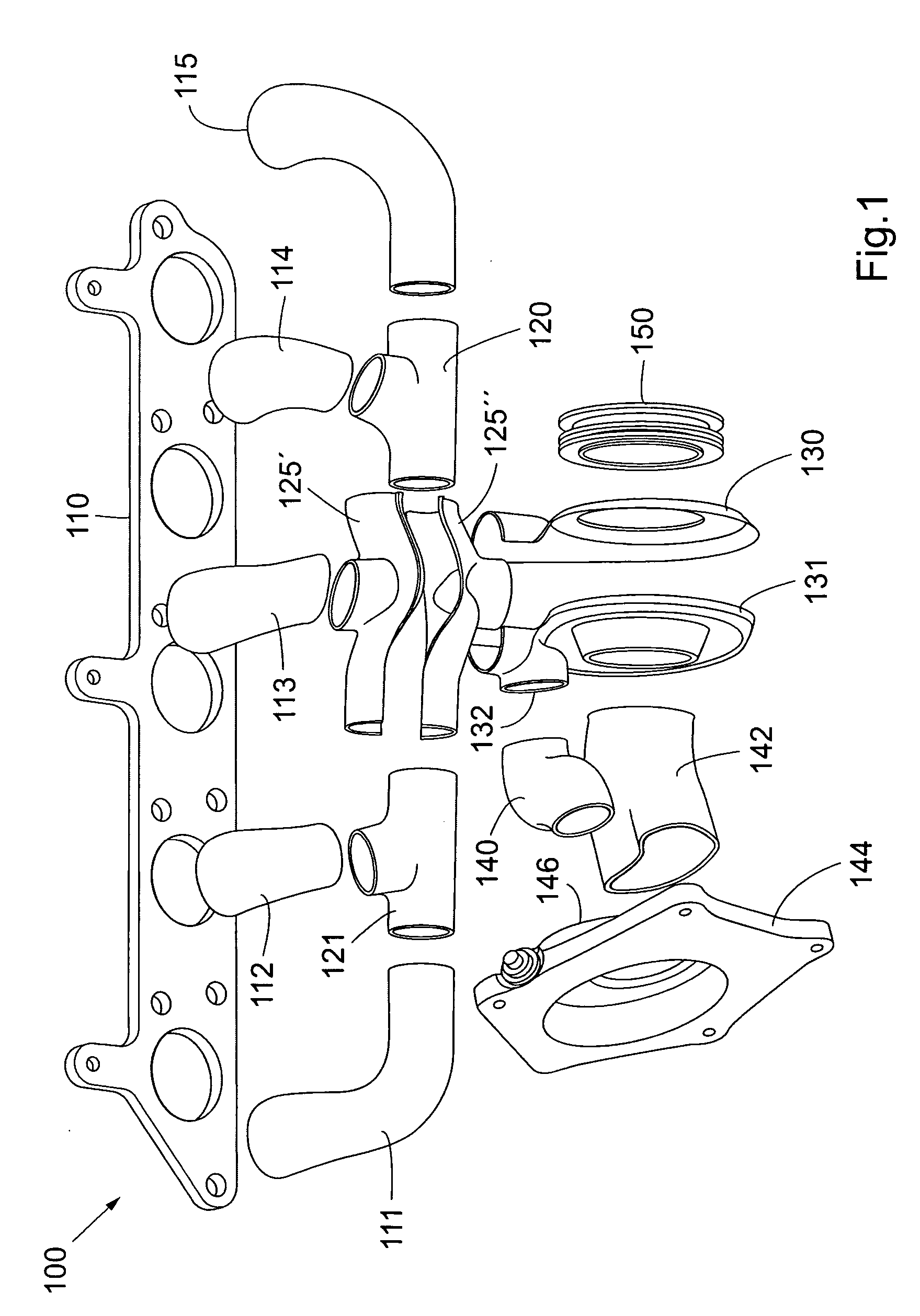
[0028] With reference to FIG. 1, an inner ductwork of a jacketed integrated turbocharger / manifold 100 comprises a manifold inlet flange 110, and five primary pipes 111, 112, 113, 114, and 115. Further, it comprises two branched pipes 120, 121, one double-branched pipe 125 consisting of an upper portion 125′ and a lower portion 125″, a first turbine housing portion 130, and a second turbine housing portion 131. The second turbine housing portion includes a waste-gate opening 132. Still further, the inner ductwork of the jacketed integrated turbocharger / manifold 100 comprises a waste-gate duct 140, an exhaust duct 142, and a turbine outlet flange 144, comprising a waste-gate 146. Finally, the inner ductwork of the jacketed integrated turbocharger / manifold 100 includes a bearing housing flange 150.

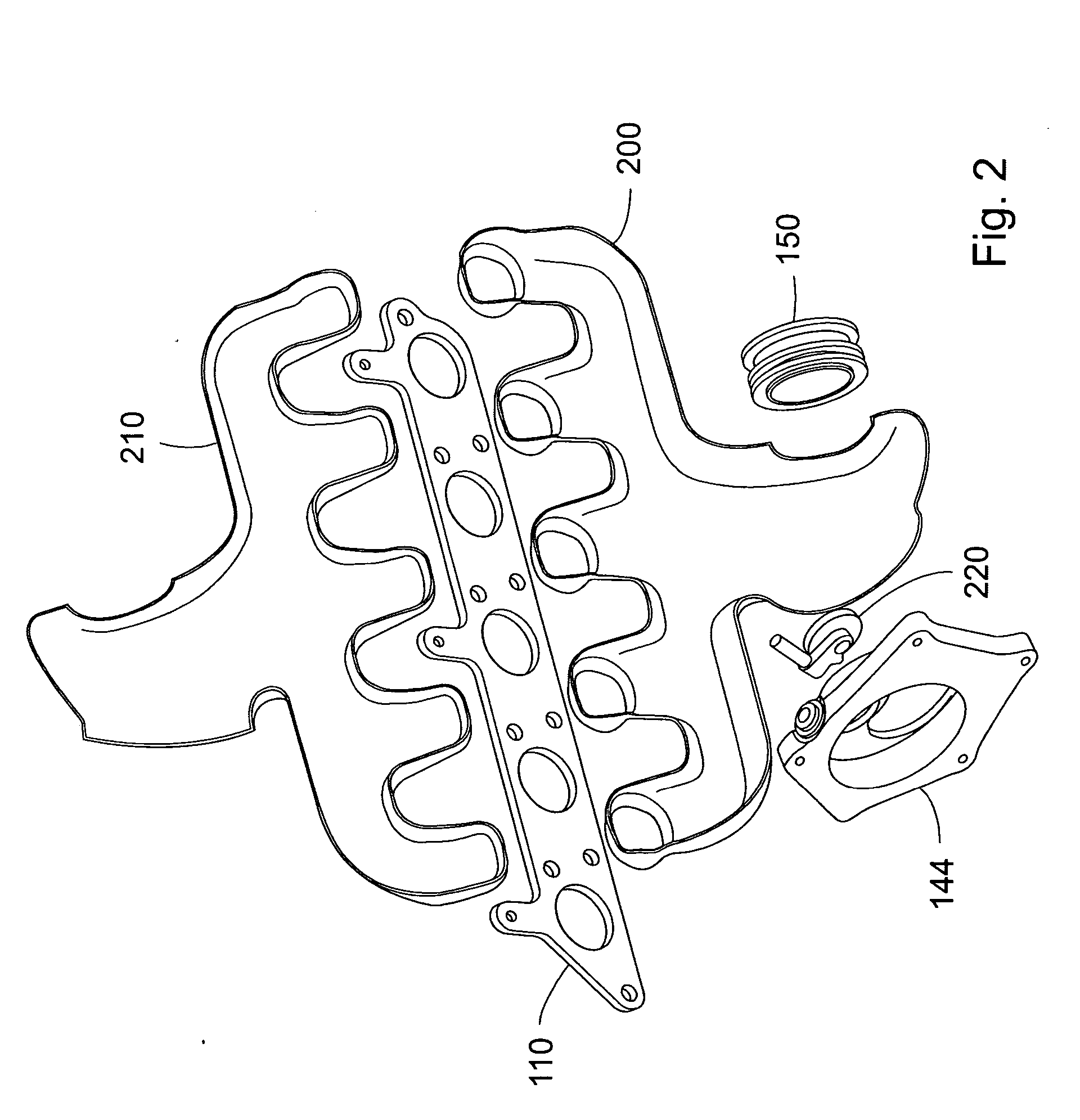
[0029] In FIG. 2, components constituting an outer housing or shell for the inner ductwork of the jacketed integrated turbocharger / manifold 100 are shown. Those components are a lower outer ...


PUM


Abstract

An integrated turbocharger/manifold (100) for an internal combustion engine comprises an inner ductwork (111-115, 120, 121, 125) and a turbine housing (130, 131). An outer shell (200, 210) covers a majority of the ductwork (111-115, 120, 121, 125) and the turbine housing (130, 131).
A method for manufacturing the integrated turbocharger/manifold comprising an inner ductwork (111-115, 120, 121, 125), a turbine housing (130, 131), a manifold inlet flange (110), a bearing housing flange (150), a turbine outlet flange (144), and two outer shell portions (200, 210) includes a first production stage wherein the manifold inlet flange (110), the bearing housing flange (150), and the turbine outlet flange (144) are held in mutually fixed positions as one of the outer shell portions (200, 210) is welded to said components.

Description

FIELD OF THE INVENTION [0001] The present invention relates to an integrated turbocharger / manifold for an internal combustion engine. The integrated turbocharger / manifold comprises an inner ductwork and a turbine housing. [0002] Further, the invention relates to a method for manufacturing an integrated turbocharger / manifold for an internal combustion engine. PRIOR ART [0003] In essence, turbocharging of an engine means that energy in the exhaust gases from a piston engine is recovered in order to increase the inlet pressure in an inlet manifold of the engine. The increased inlet pressure allows a higher power density for the engine, which means that a higher power and torque can be extracted from an engine of a given swept volume. [0004] Turbocharged engines have been used extensively for the last decades as a way to increase torque and power output from piston engines of a given swept volume. Turbocharging has a number of advantages over so called naturally aspirated (NA) engines, ...

Claims


Application Information

Patent Timeline
Patent Type & Authority Applications(United States)
IPC IPC(8): F01N13/10F02B37/02F02B67/10
CPCF01N13/102Y02T10/144F02B67/10F02B37/02Y02T10/12
Inventor BJORNSSON, HAKAN SR.
Owner FORD GLOBAL TECH LLC
Why Eureka
Try Eureka