Apparatus and methods for microchannel cooling of semiconductor integrated circuit packages

a technology of integrated circuits and cooling apparatuses, which is applied in the direction of power cables, semiconductor/solid-state device details, cables, etc., can solve the problems of increasing system performance limitations, increasing power density, and increasing the difficulty of efficiently removing heat, so as to achieve efficient and low operating pressure microchannel cooling, uniform flow and distribution of coolant fluid, and minimize pressure drop

Inactive Publication Date: 2007-03-13
INT BUSINESS MASCH CORP
View PDF17 Cites 91 Cited by
  • Summary
  • Abstract
  • Description
  • Claims
  • Application Information

AI Technical Summary

Benefits of technology

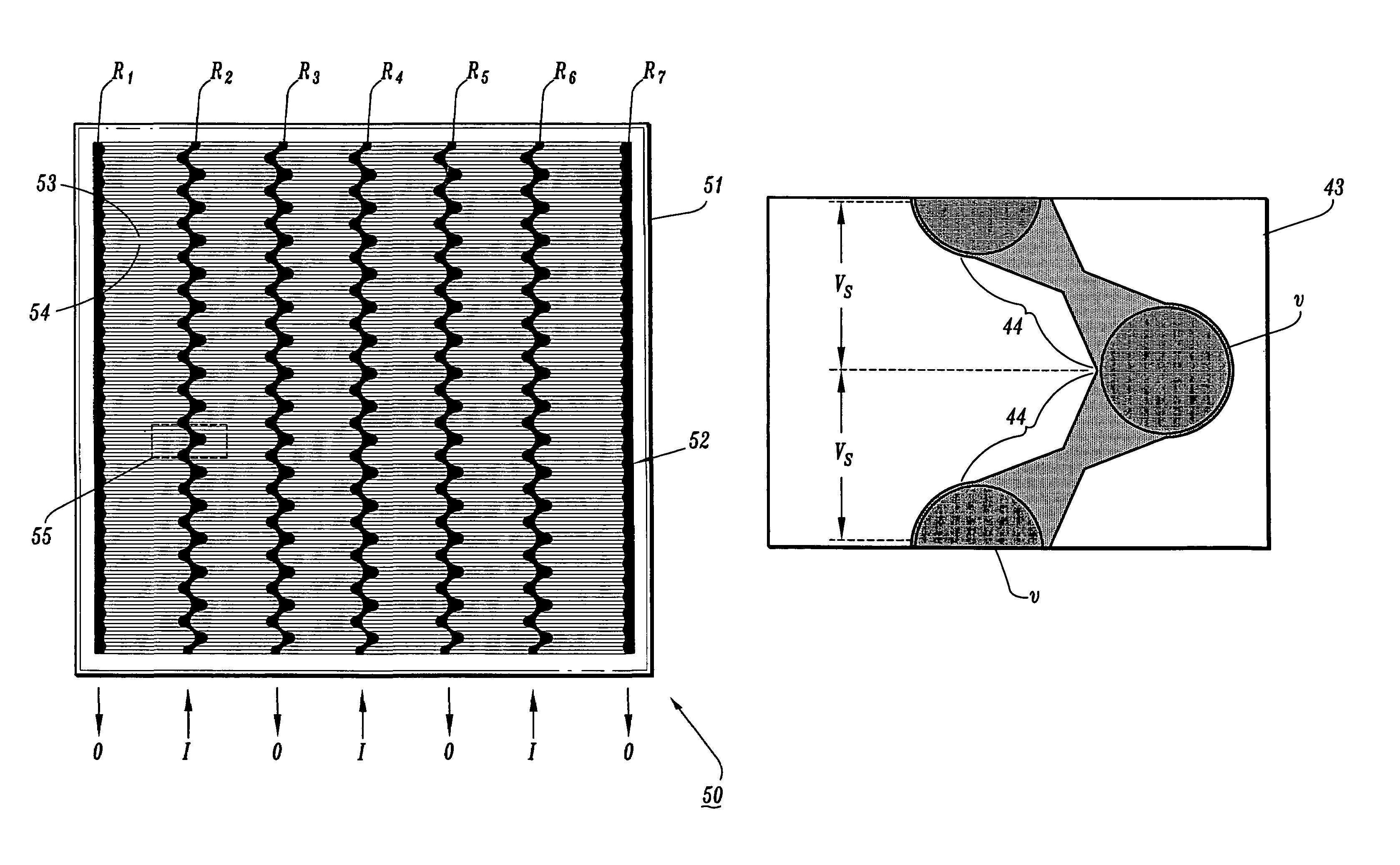
[0013]Exemplary embodiments of the invention generally include apparatus and methods for cooling of electronic devices and, in particular, apparatus and methods for microchannel cooling of IC (integrated circuit) chips mounted face down on a package substrate. More specifically, exemplary embodiments of the invention include microchannel cooling apparatus, including integrated microchannel heat sink devices and fluid distribution manifold structures, which are designed to provide uniform flow and distribution of coolant fluid and minimize pressure drops along coolant flow paths to thereby enable efficient and low operating pressure microchannel cooling of high power density electronic devices.

Problems solved by technology

The ability to efficiently remove heat becomes increasing problematic as chip geometries are scaled down and operating speeds are increased, resulting in increased power density.
Although IC chip modules are being continually designed to operate at higher clock frequencies, increased system performance is becoming limited primarily by the ability to effectively remove heat from such IC chip modules.
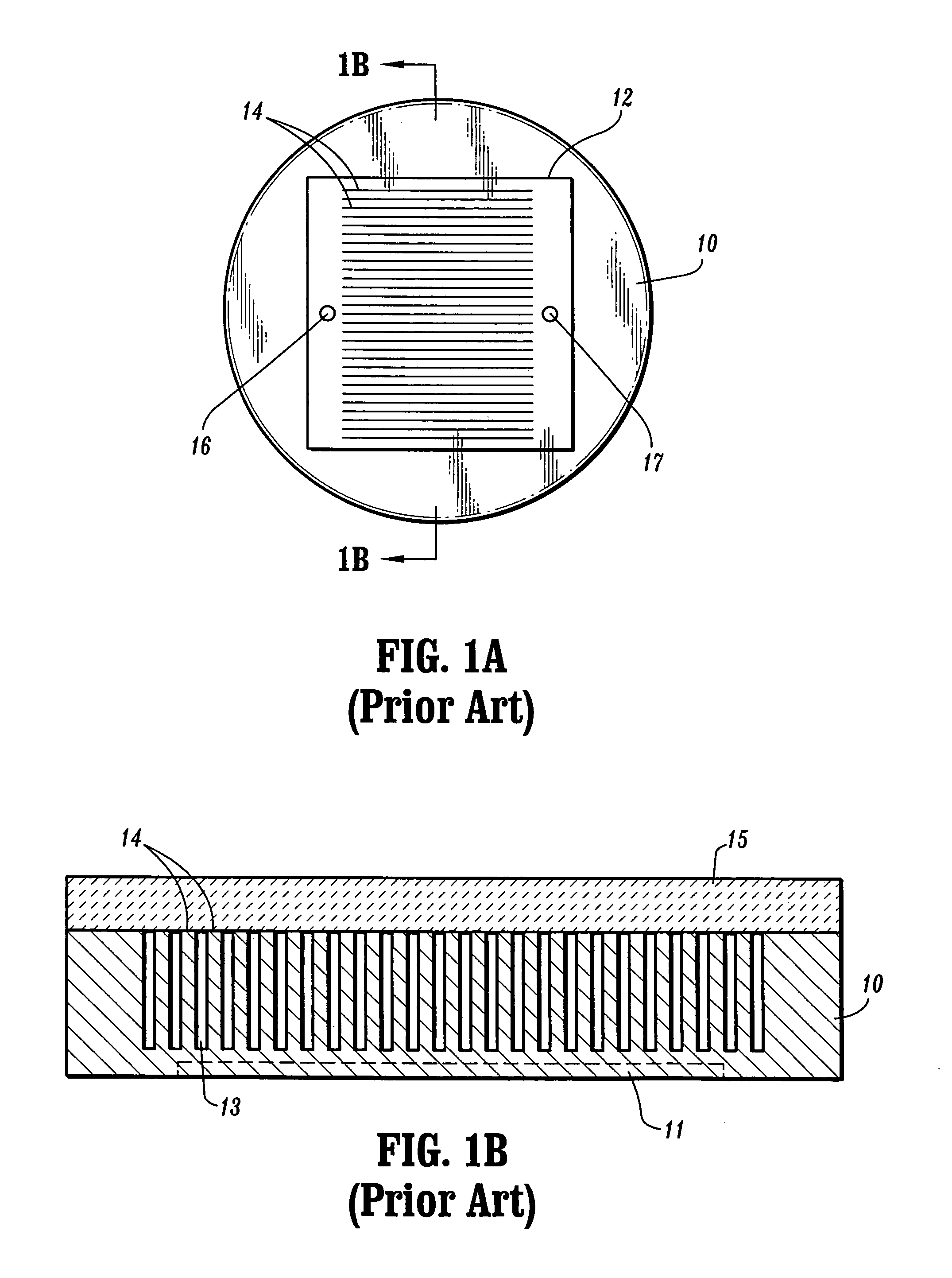
There are a number of disadvantages associated with the cooling apparatus depicted in FIGS. 1A and 1B.
For instance, such design results in significant pressure drops and non-uniform flow distribution due to, e.g., the use of one heat exchanger zone (with long channel length) between the input port (16) and the output port (17), and having an input port (16) and output port (17) with a cross sectional area that is smaller than the total microchannel cross sectional area.
Furthermore, the process of forming the fins (14) and channels (13) directly in the non-active surface of the IC chip (10) can result in reduced yield for the chips (10), which is not desirable especially for expensive chips such as microprocessors.
Indeed, if the microchannel cooler fails or leaks, the chip, which is much more expensive than the cooler in the case of a high performance processor, is lost along with the microchannel cooler.
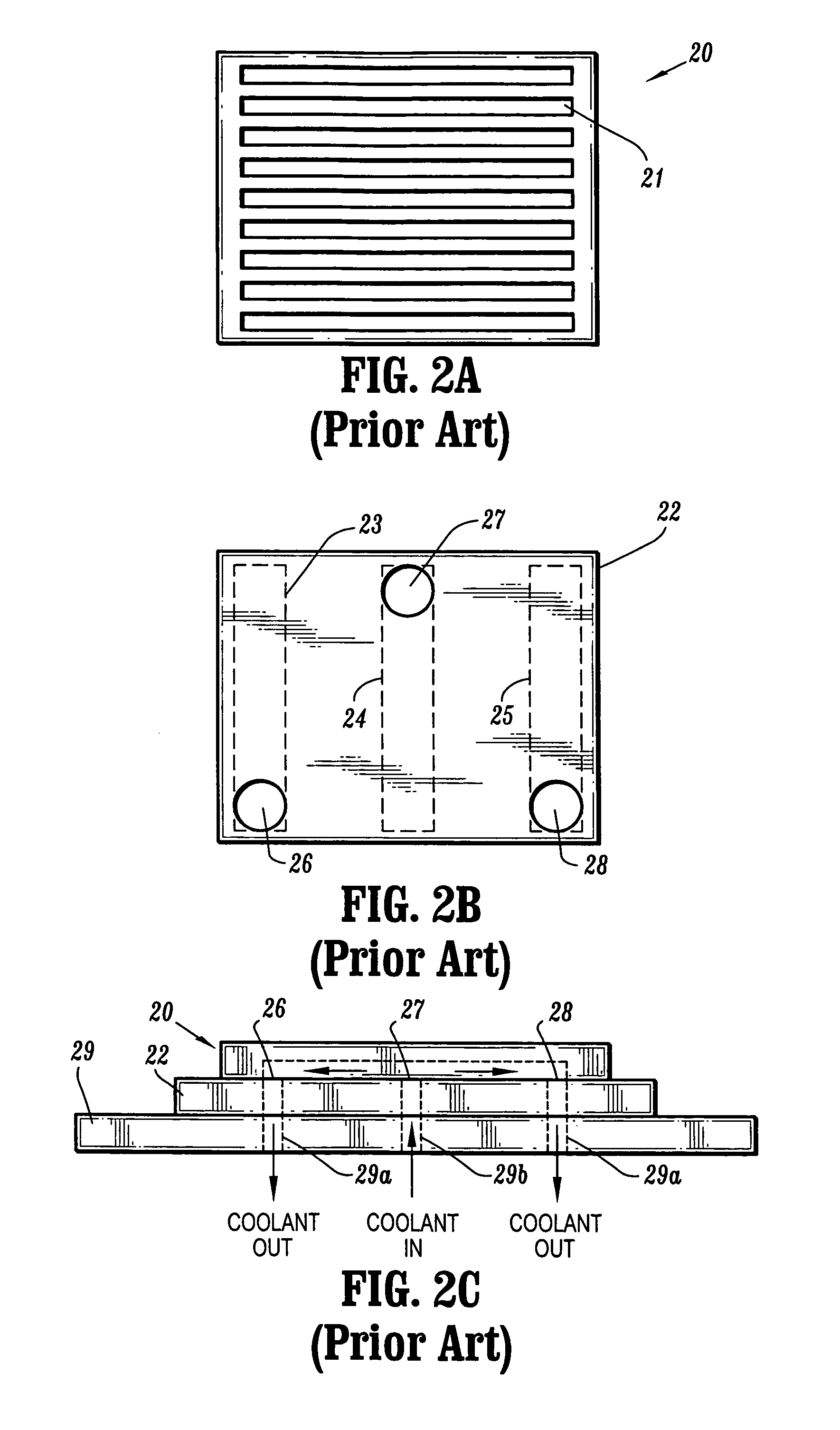
There are a number of disadvantages with the conventional microchannel cooling apparatus depicted in FIGS. 2A˜2C.
Moreover, such design results in significant pressure drops and non-uniform flow distribution, which result from (i) the input and output ports (26, 27, 28) having a smaller cross sectional area than the total microchannel cross sectional area, (ii) the manifolds (23, 24, 25) having grooves which are of constant cross section feeding the microchannels (21) and (iii) having the microchannels (21) continue below the inlet manifold groove (24) when two outlet manifold grooves (23, 25) are used.
There are disadvantages associated with the microchannel cooling apparatus depicted in FIGS. 3A and 3B.
Moreover, if a cover manifold (34) was formed with multiple coolant delivery channels (e.g., 34a) for multiple heat exchanger zones to reduce the pressure drop, the cover manifold (34) would be fragile and likely to break during fabrication, thereby reducing manufacturing yield.
Furthermore, the coolant supply manifold (35) design of FIG. 3B can result in large pressure drops and significant non-uniform flow distribution due to the channels, which feed a given column of four microchannel inlets, having a constant cross-sectional area.
For low cooling capability, like less than 50 W / cm2, the water flow requirements are low, and it is possible to have both manifold channels and microchannels with laminar flow regimes, but at high flows this is not possible since the microchannels will require flow regimes with Reynolds number in the 100–200 range, then, the flow regime in the manifold channel will not be laminar.

Method used


Image

  • Apparatus and methods for microchannel cooling of semiconductor integrated circuit packages
  • Apparatus and methods for microchannel cooling of semiconductor integrated circuit packages
  • Apparatus and methods for microchannel cooling of semiconductor integrated circuit packages

Examples


Embodiment Construction

[0030]Exemplary embodiments of the invention as described herein generally include apparatus and methods for cooling of electronic devices and, in particular, apparatus and methods for microchannel cooling of IC (integrated circuit) chips mounted face down on a package substrate. In general, an apparatus for microchannel cooling an electronic device according to one exemplary embodiment of the invention comprises an integrated microchannel cooler device (or microchannel heat sink) that is thermally bonded to a non-active surface of an IC chip mounted face down on a package substrate, and a fluid distribution manifold device, which is removably coupled to the integrated microchannel device via a mechanically compliant gasket, to deliver coolant fluid to / from the integrated microchannel device. As explained below, microchannel cooling apparatus and methods according to various exemplary embodiments of the invention implement fluid distribution and flow mechanisms which foster uniform ...


PUM


Abstract

Apparatus and methods are provided for microchannel cooling of electronic devices such as IC chips, which enable efficient and low operating pressure microchannel cooling of high power density electronic devices. Apparatus for microchannel cooling include integrated microchannel heat sink devices and fluid distribution manifold structures that are designed to provide uniform flow and distribution of coolant fluid and minimize pressure drops along coolant flow paths.

Description

[0001]This invention was made with Government support under Contract No. H98230-04-C-0920 awarded by the Maryland Procurement Office. The Government has certain rights to the invention.TECHNICAL FIELD OF THE INVENTION[0002]The present invention relates generally to apparatus and methods for cooling electronic devices. More specifically, the present invention relates to microchannel cooling apparatus and methods which provide improved fluid distribution and flow mechanisms for efficient cooling of semiconductor integrated circuit (IC) chip packages.BACKGROUND[0003]In the design and manufacture of semiconductor IC (integrated circuit) chip packages and modules, it is imperative to implement mechanisms that can effectively remove heat generated by IC chip devices (such as microprocessors) to ensure continued reliable operation of such devices. Indeed, heat removal is particularly important for computer processor chips that are disposed in SCM (single chip modules) or MCMs (multichip mo...

Claims


Application Information

Patent Timeline
Patent Type & Authority Patents(United States)
IPC IPC(8): H05K7/20
CPCF28F3/12F28F9/028F28F13/06H01L23/473F28F2260/02H01L2924/0002H01L2924/00
Inventor BEZAMA, RASCHID JOSECOLGAN, EVAN GEORGEMAGERLEIN, JOHN HAROLDSCHMIDT, ROGER RAY
Owner INT BUSINESS MASCH CORP
Why Eureka
Try Eureka