Gas storage apparatus

a technology of gas storage and gas pipes, applied in the direction of domestic cooling apparatus, lighting and heating apparatus, separation processes, etc., can solve the problems of insufficient attention to specific design, complex arrangement of pipes used to circulate coolant or other fluids, etc., and achieve the effect of improving heat exchange efficiency

Inactive Publication Date: 2006-09-26
TOYOTA JIDOSHA KK +1
View PDF15 Cites 87 Cited by
  • Summary
  • Abstract
  • Description
  • Claims
  • Application Information

AI Technical Summary

Benefits of technology

[0006]The present invention was created in view of this problem with the conventional art, and an object thereof is to improve heat exchange efficiency when a coolant is used in a gas storage apparatus that incorporates multiple gas storage tanks that contain a storing / adsorbing material.

Problems solved by technology

When the number of gas storage tanks is increased, thereby realizing a gas storage apparatus incorporating multiple gas storage tanks, there is a risk that the arrangement of the pipes used to circulate the coolant or other fluid will become complex.
However, sufficient attention has not been paid to the specific design of the arrangement of the pipes used to circulate coolant or other fluid in a gas storage apparatus incorporating multiple gas storage tanks.

Method used


Image

  • Gas storage apparatus
  • Gas storage apparatus
  • Gas storage apparatus

Examples


second embodiment

C. SECOND EMBODIMENT

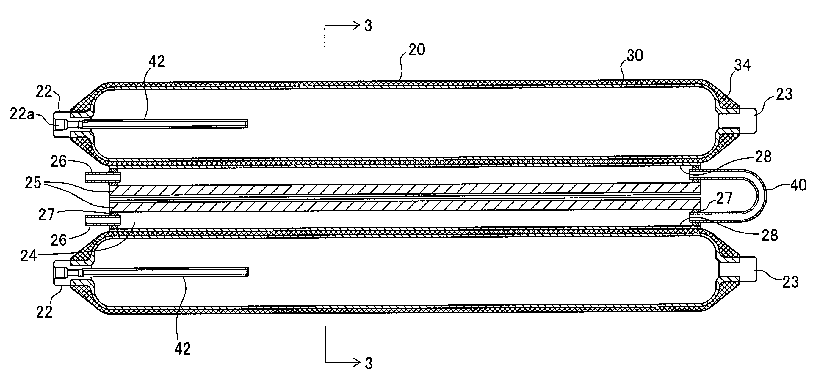
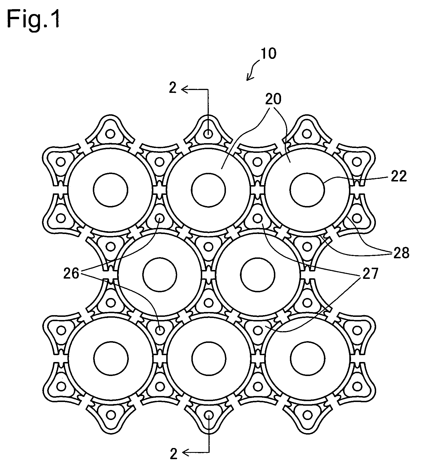
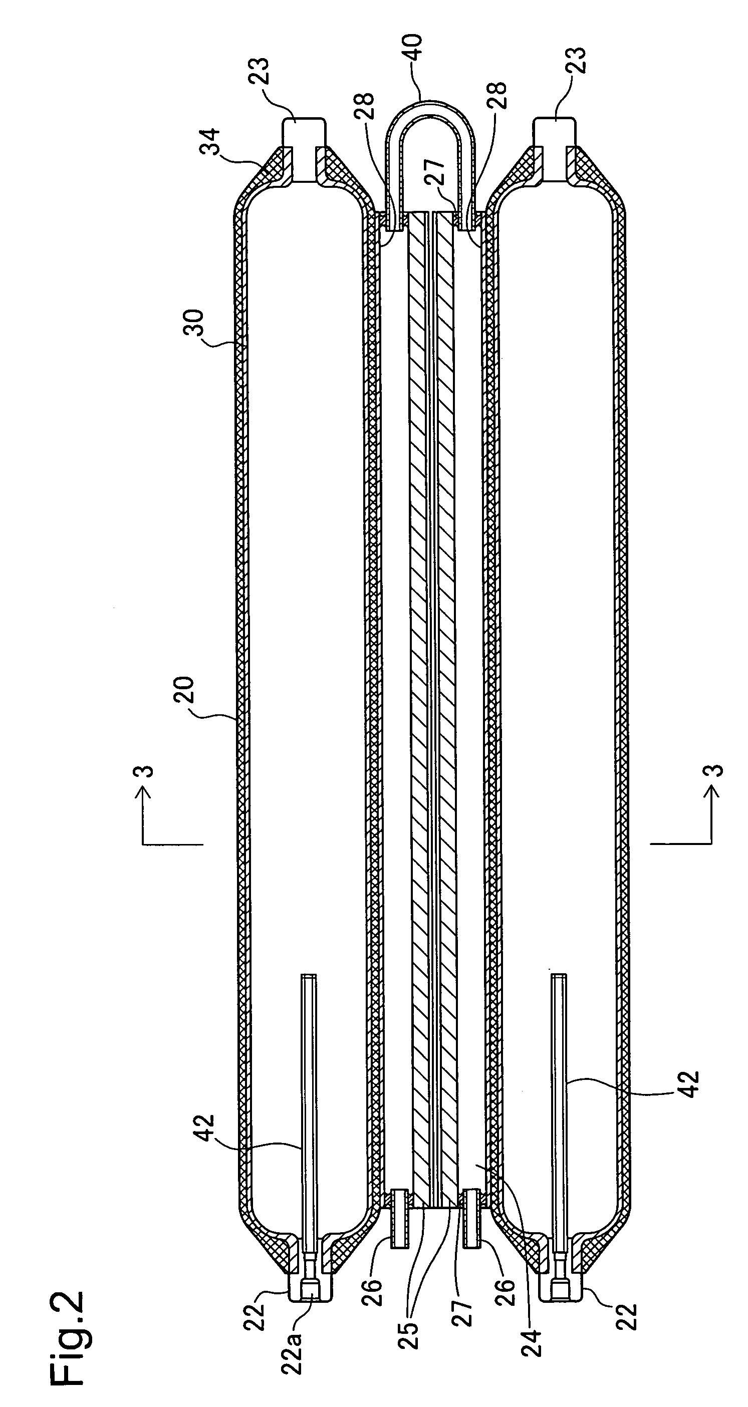
[0062]FIG. 5 is an explanatory drawing showing the basic construction of a hydrogen storage apparatus of a second embodiment based on a horizontal cross-section similar to that of FIG. 3. Because the hydrogen storage apparatus of the second embodiment has a construction similar to that of the hydrogen storage apparatus 10 of the first embodiment, identical reference numbers will be used in FIG. 5 to indicate common components with the first embodiment. Furthermore, because the interior construction of the coolant path formed between the hydrogen storage tanks 20 in the hydrogen storage apparatus of the second embodiment differs from the equivalent construction in the first embodiment, FIG. 5 focuses on the construction of such coolant path.

[0063]In the hydrogen storage apparatus of the second embodiment, a barrier rod 44 is disposed inside the coolant path 124 formed between three hydrogen storage tanks 20 in the same manner as the coolant path 24 of the first em...

third embodiment

D. THIRD EMBODIMENT

[0069]FIG. 11 comprises explanatory drawings of the construction of a coolant path in a hydrogen storage apparatus of a third embodiment. Because the hydrogen storage apparatus of the third embodiment has a construction similar to that of the hydrogen storage apparatus 10 of the first embodiment, only the different components will be described. Furthermore, the identical reference numbers will be used in FIG. 11 to indicate common components with the first embodiment. FIG. 11(A) is a perspective drawing showing the construction of a heat transfer plate 528 that is used by the hydrogen storage apparatus of the third embodiment in place of the heat transfer plate 28 of the first embodiment. FIG. 11(B) is an explanatory drawing showing a cross-sectional view of the coolant path 524 formed between three hydrogen storage tanks 20 of the hydrogen storage apparatus of the third embodiment.

[0070]Each heat transfer plate 528 of the hydrogen storage apparatus of the third e...

fourth embodiment

E. FOURTH EMBODIMENT

[0073]FIG. 12 is an explanatory drawing showing a horizontal cross-sectional view of coolant paths of a hydrogen storage apparatus of a fourth embodiment. Because the hydrogen storage apparatus of the fourth embodiment has a construction similar to that of the hydrogen storage apparatus 10 of the first embodiment, identical reference numbers will be used in FIG. 12 to indicate common components with the first embodiment. Furthermore, because the interior construction of the coolant path formed between the hydrogen storage tanks 20 in the hydrogen storage apparatus of the fourth embodiment differs from the equivalent construction in the first embodiment, FIG. 12 focuses on the construction of such coolant path.

[0074]In the hydrogen storage apparatus of the fourth embodiment, while a coolant path is formed in the empty space formed between three hydrogen storage tanks 20 as in the above embodiments, rather than a single coolant path occupying the entire empty space...


PUM

PropertyMeasurementUnit
elasticaaaaaaaaaa
cross-sectional areaaaaaaaaaaa
adsorptionaaaaaaaaaa

Abstract

A hydrogen storage apparatus that includes multiple gas storage tanks that each house a storing / adsorbing material and through the interior of which a fluid travels is provided. The gas storage apparatus 10 includes roughly cylindrical gas storage tanks 20 that house hydrogen-storing alloy. The multiple gas storage tanks 20 are disposed longitudinally parallel to each other in an ordered fashion such that roughly triangular prism-shaped empty spaces are formed between multiple adjacent hydrogen storage tanks 20. Coolant paths through which coolant flows are formed in these roughly triangular prism-shaped empty spaces. These coolant paths are thermally connected to the hydrogen-storing alloy in the gas storage tanks 20 via constituent members of the gas storage tanks 20 and via heat transfer plates 28 disposed on the gas storage tanks 20.

Description

BACKGROUND OF THE INVENTION[0001]1. Field of the Invention[0002]The present invention relates to a gas storage apparatus that includes gas tanks for storage of gas.[0003]2. Description of the Related Art[0004]Various types of gas tanks for storage of gas have been proposed. One known method for storing gas involves the occlusion or adsorption of gas in a prescribed storing / adsorbing material. For example, a hydrogen storage tank that stores hydrogen gas using a hydrogen-storing material stored inside the tank is known. In addition, a hydrogen storage tank is known wherein a heat transfer medium channel is disposed on the outer circumference of the tank and a thermal conduction material that transfers heat between the heat transfer medium inside the heat transfer medium channel and the hydrogen-storing material is disposed inside the tank.[0005]In a gas storage apparatus equipped with a gas storage tank, the number of gas storage tanks may be increased in order to increase gas storag...

Claims


Application Information

Patent Timeline
Patent Type & Authority Patents(United States)
IPC IPC(8): F17C11/00C01B3/00F25D25/00
CPCC01B3/0005F17C11/005F17C2205/013Y02E60/327F17C2227/0337Y02E60/321F17C2223/0123Y02E60/32
Inventor KIMBARA, MASAHIKOMORI, DAIGORONITO, TAKEHIROKUBO, HIDEHITOTOH, KEIJI
Owner TOYOTA JIDOSHA KK
Why Eureka
Try Eureka