Double-wall pipe and refrigerant cycle device using the same

Inactive Publication Date: 2006-05-11
DENSO CORP +1
View PDF19 Cites 71 Cited by
  • Summary
  • Abstract
  • Description
  • Claims
  • Application Information

AI Technical Summary

Benefits of technology

[0022] Accordingly, a turbulent flow of the fluid can be easily generated in the passage between the inner pipe and the outer pipe, and the turbulent flow of the fluid enhances the heat transfer efficiency. Consequently, heat can be efficiently transferred between the fluid flowing through the inner pipe and the fluid flowing through the passage between the inner pipe and the outer pipe.
[0023] According to another aspect of the present invention, in a double-wall pipe constructed with an outer pipe and an inner pipe inserted into the outer pipe, the inner pipe is provided in its wall with a groove portion extending from a first end par

Problems solved by technology

Since the inner pipe has a small surface area, heat cannot be efficiently transferred from one to the other of th

Method used


Image

  • Double-wall pipe and refrigerant cycle device using the same
  • Double-wall pipe and refrigerant cycle device using the same
  • Double-wall pipe and refrigerant cycle device using the same

Examples


first embodiment

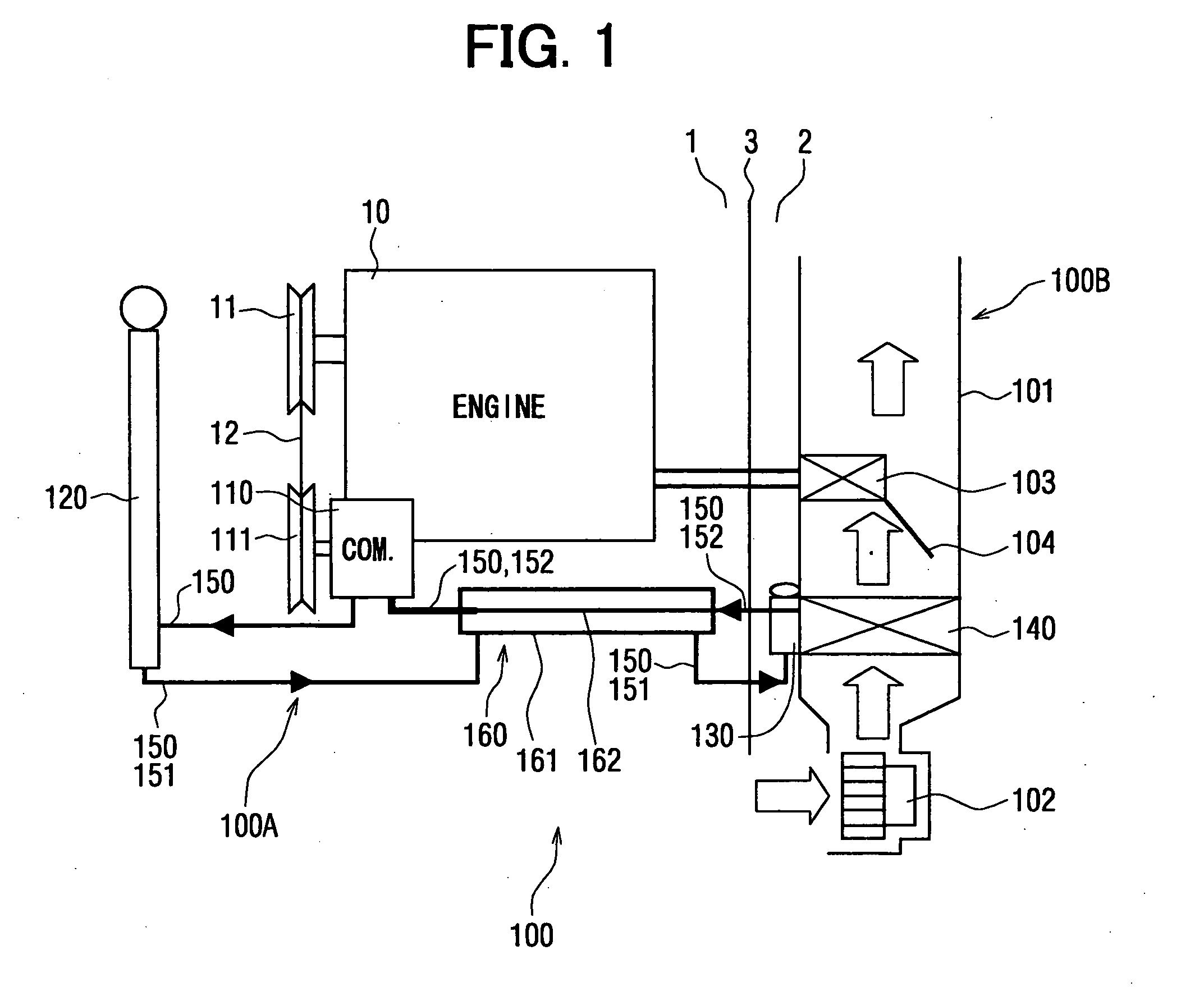
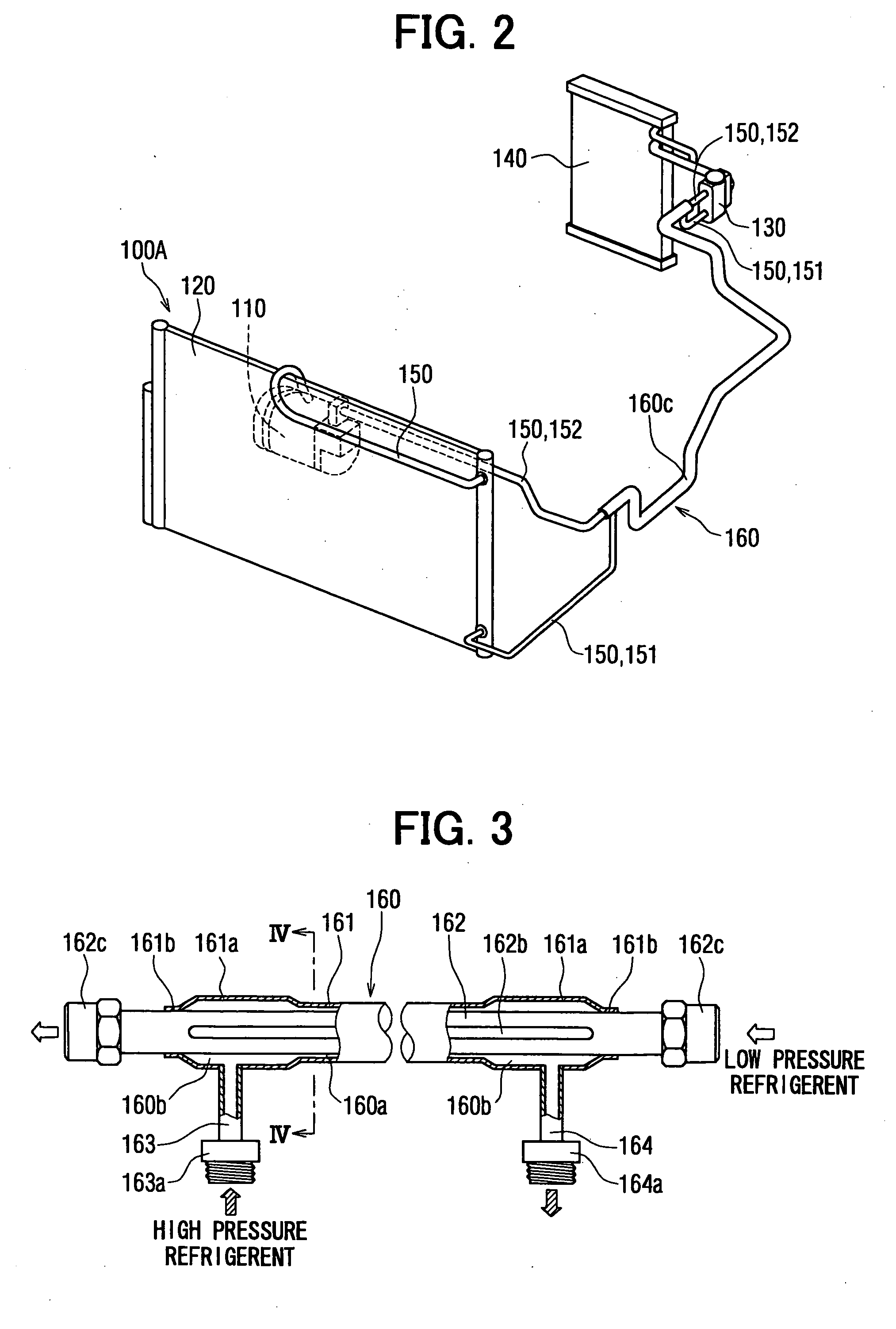
[0042] In this embodiment, a double-wall pipe 160 for carrying a refrigerant is typically used for a refrigerant cycle device 100A for a vehicle air conditioning system 100. The double-wall pipe 160 will be described with reference to FIGS. 1 to 4.

[0043] A vehicle has an engine room 1 holding an engine 10 therein and a passenger compartment 2 separated from the engine room 1 by a dash panel 3. The air conditioning system 100 has the refrigerant cycle device 100A including an expansion valve 130 and an evaporator 140, and an interior unit 100B. Components of the refrigerant cycle device 100A excluding the expansion valve 130 and the evaporator 140 are disposed in a predetermined mounting space of the engine room 1. The interior unit 100B is arranged in an instrument panel placed in the passenger compartment 2.

[0044] The interior unit 100B has components including a blower 102, the evaporator 140 and a heater 103, and an air conditioner case 101 housing the components of the interio...

second embodiment

[0070]FIG. 6 shows a part of a double-wall pipe 160 of the second embodiment.

[0071] Referring to FIG. 6, the double-wall pipe 160 in the second embodiment according to the present invention has expanded passages 160b formed in longitudinal end parts thereof and different from those of the double-wall pipe 160 in the first embodiment.

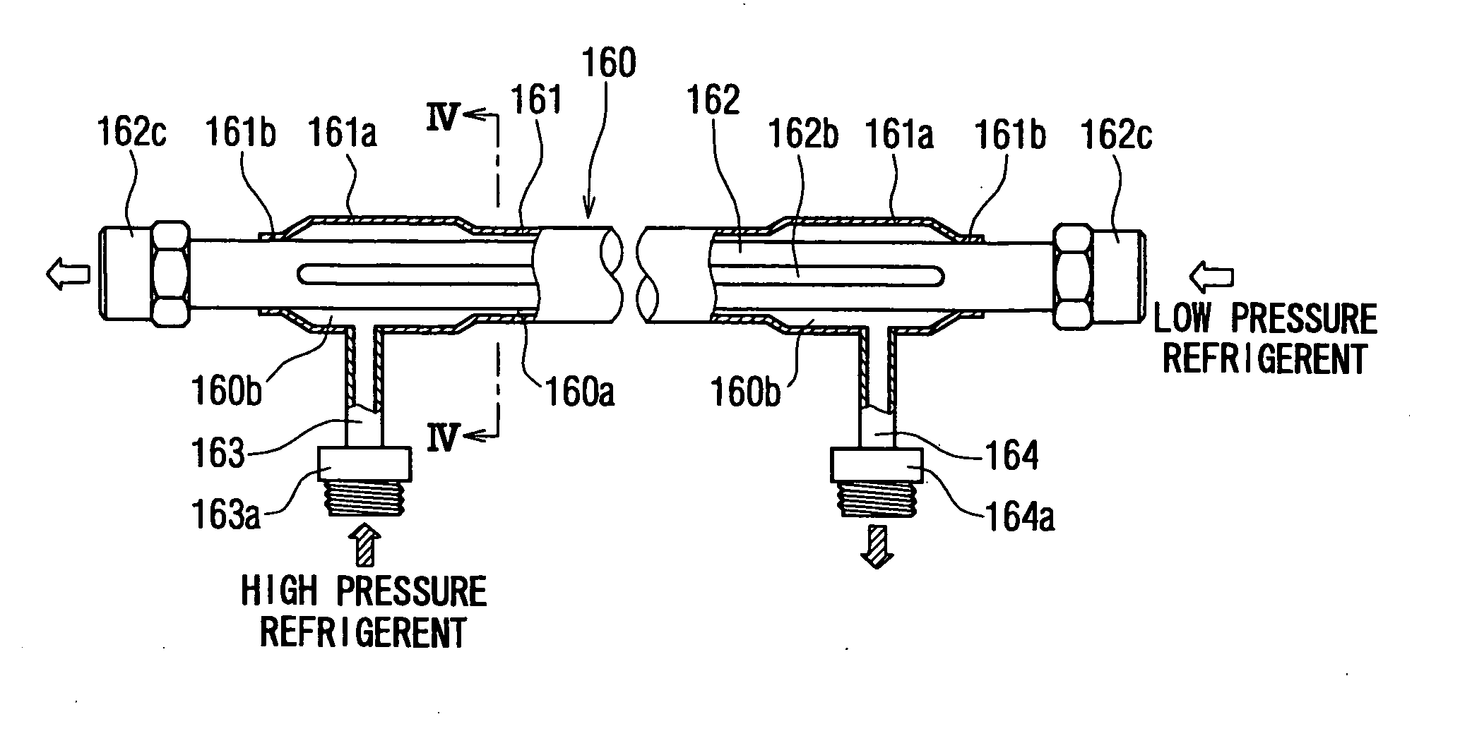
[0072] Since the expanded passages 160b formed near an inlet pipe 163 and an outlet pipe 164 in the longitudinal end parts of the double-wall pipe 160, respectively, are the same in shape, only the expanded passage 160b formed near an inlet pipe 163 will be described. A depression 162a (recess portion) is formed in an inner pipe 162 by radially depressing a circumferential part of the inner pipe 162 to define the expanded passage 160b. Because the depression 162a is formed in the inner pipe 162, a narrow part is formed in the inner pipe 162 due to the depression 162a. The expanded passages 160b at the junction between the inlet pipe 163 and a passage 1...

third embodiment

[0075]FIG. 7 shows an inner pipe 160 and an outer pipe 161 of the third embodiment. Referring to FIG. 7, a double-wall pipe 160 in the third embodiment according to the present invention has an inner pipe 162 provided with three helical grooves 162d formed in the shape of a three-thread screw instead of the straight grooves 162a of the inner pipe 162 of the double-wall pipe 160 in the first embodiment. Multiple helical grooves, that is, more than one helical groove, may be formed in the shape of a multithread screw and arranged at equal or predetermined pitches or a single helical groove may be formed in the inner pipe 162 instead of the three helical grooves 162d. The three helical grooves 162d are formed by deforming the wall of the inner pipe 162. The three helical grooves 162d form helical ridges inside the inner pipe 162. The three helical grooves 162d are parallel to each other.

[0076] The three helical grooves 162d winding around the inner pipe 162 increase the bending rigidi...


PUM

PropertyMeasurementUnit
Pressureaaaaaaaaaa
Diameteraaaaaaaaaa
Shapeaaaaaaaaaa

Abstract

A double-wall pipe includes an outer pipe provided with first and second openings, respectively, at first and second end parts of the outer pipe in a pipe longitudinal direction, and an inner pipe inserted in the outer pipe to define a passage between the outer pipe and the inner pipe. An inlet portion is connected to the outer pipe to communicate with the passage through the first opening, and an outlet portion is connected to the outer pipe to communicate with the passage through the second opening. In the double-wall pipe, the outer pipe and the inner pipe can be disposed to define an expanded portion having an expanded sectional area in the first passage, and the expanded portion can be provided at least at a portion near the inlet portion and the outer portion. The inner pipe can be provided with plural grooves in the double-wall pipe.

Description

CROSS REFERENCE TO RELATED APPLICATION [0001] This application is based on Japanese Patent Applications No. 2004-325522 filed on Nov. 9, 2004, No. 2004-325521 filed on Nov. 9, 2004, No. 2005-112825 filed on Apr. 8, 2005, No. 2005-136390 filed on May 9, 2005, and No. 2005-263967 filed on Sep. 12, 2005, the contents of which are incorporated herein by reference. FIELD OF THE INVENTION [0002] The present invention relates to a double-wall pipe constructed with an inner pipe defining an inner passage and an outer pipe enveloping the inner pipe so as to define an outer passage between the outer pipe and the inner pipe. The double-wall pipe can be suitably used for a refrigerant cycle device, for example. BACKGROUND OF THE INVENTION [0003] A double-wall pipe is used in a refrigerant cycle device for a vehicle air conditioning system, for example. [0004] A double-wall pipe disclosed in, for example, JP-A-2001-277842 is formed by combining a high-pressure refrigerant pipe extending between ...

Claims


Application Information

Patent Timeline
IPC IPC(8): F25B1/00F16L9/18F25B41/00
CPCF16L7/00F16L9/18F25B40/00F28D7/106F28F1/06Y10T29/49361F28F1/426F28F2210/06B23P17/02Y10T29/49428Y10T29/49826F28F1/42F25B1/00F28D7/10F28F1/00
Inventor NAKAMURA, FUMIAKITAKANO, YOSHIAKIISHIZAKA, NAOHISATAKEUCHI, HIROTSUGUOCHIAI, KINJI
Owner DENSO CORP
Why Eureka
Try Eureka