Fuel vaporizer for a reformer type fuel cell system

a fuel cell system and reformer technology, applied in the field of vaporizers, can solve the problems of increasing the response time of the fuel cell system to the demands of the operator, slowing down the response time of the fuel cell system, and increasing the susceptibility of the vaporizer to thermal fatigue, so as to reduce the thermal stress within the vaporizer, improve the response time of the fuel cell system, and reduce the effect of vaporizer efficiency

Inactive Publication Date: 2006-06-20
MODINE MFG CO
View PDF22 Cites 70 Cited by
  • Summary
  • Abstract
  • Description
  • Claims
  • Application Information

AI Technical Summary

Benefits of technology

[0009]It is a principal object of the invention to improve the response time of a fuel cell system of the reformer type without decreasing the core size of the fuel vaporizer to the point where such would lead to a commensurate decrease in the effectiveness of the vaporizer. It is also a principal object of the invention to accomplish the foregoing while at the same, reducing thermal stress within the vaporizer to thereby improve its useful life.
[0011]The absence of any heat transfer enhancements in the hot fluid flow path adjacent the second zone minimizes thermal stress in the area where the innards of the vaporizer are subject to the highest temperatures of the hot fluid and are not substantively cooled by the cold fluid, i.e. the fuel, due to the superheated condition of the fuel in the second zone. The absence of heat transfer enhancement adjacent the second zone also allows for additional enhancements to be located in the first and / or third zone to improve heat transfer efficiency in such zones to the point where the core size of the vaporizer may actually be reduced to improve response time in the fuel cell system with which the vaporizer is used without reducing heat transfer efficiency and / or increasing pressure drop.

Problems solved by technology

As it happens, the greater the charge of fuel in the fuel vaporizer, the slower the response of the fuel cell system to demands of the operator.
However, as this length is increased, response time also increases as a result because the fuel charge in the vaporizer increases as a result of the increased volume that accompanies increased length.
This, in turn, increases the susceptibility of the vaporizer to thermal fatigue.

Method used


Image

  • Fuel vaporizer for a reformer type fuel cell system
  • Fuel vaporizer for a reformer type fuel cell system
  • Fuel vaporizer for a reformer type fuel cell system

Examples


Embodiment Construction

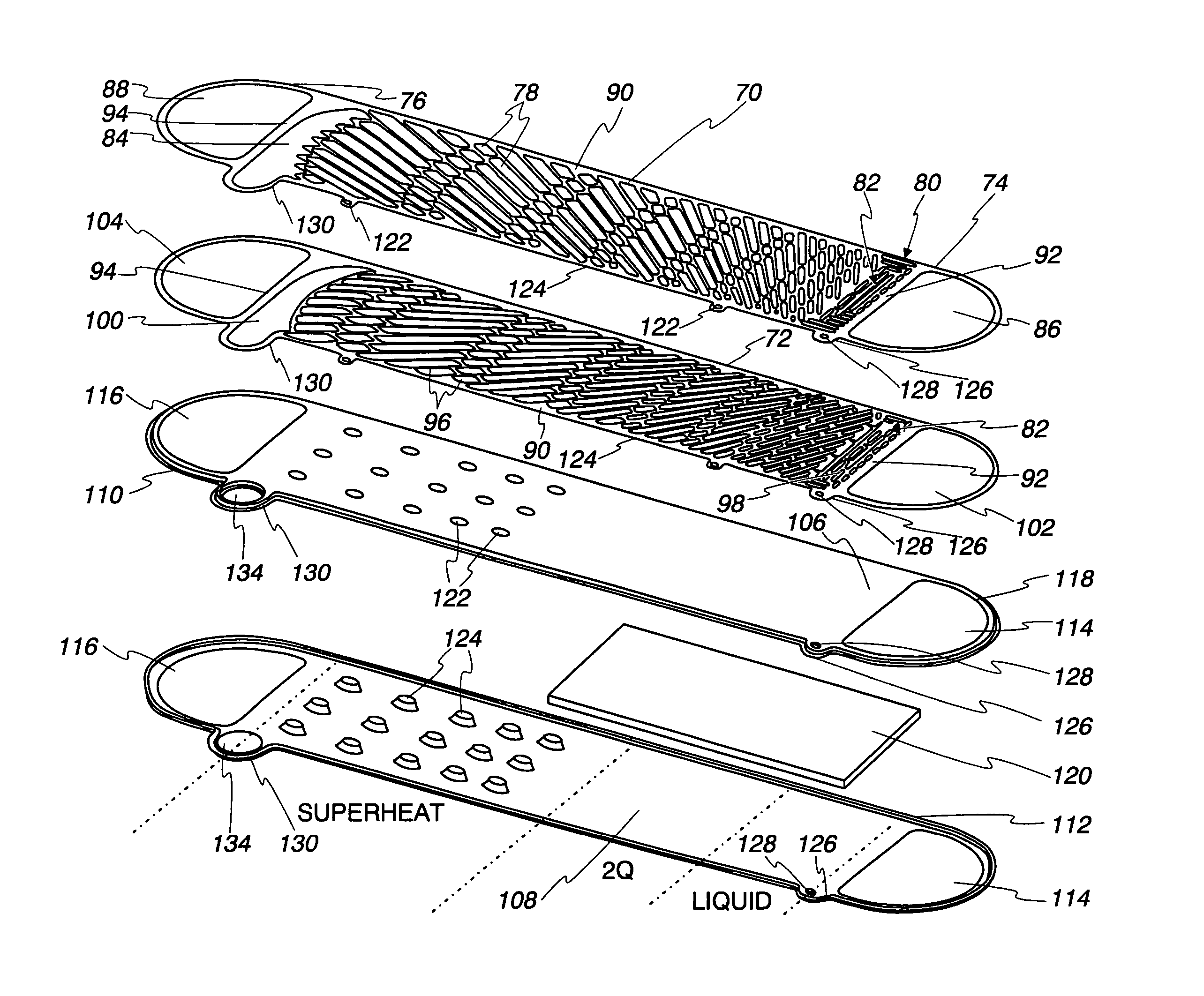
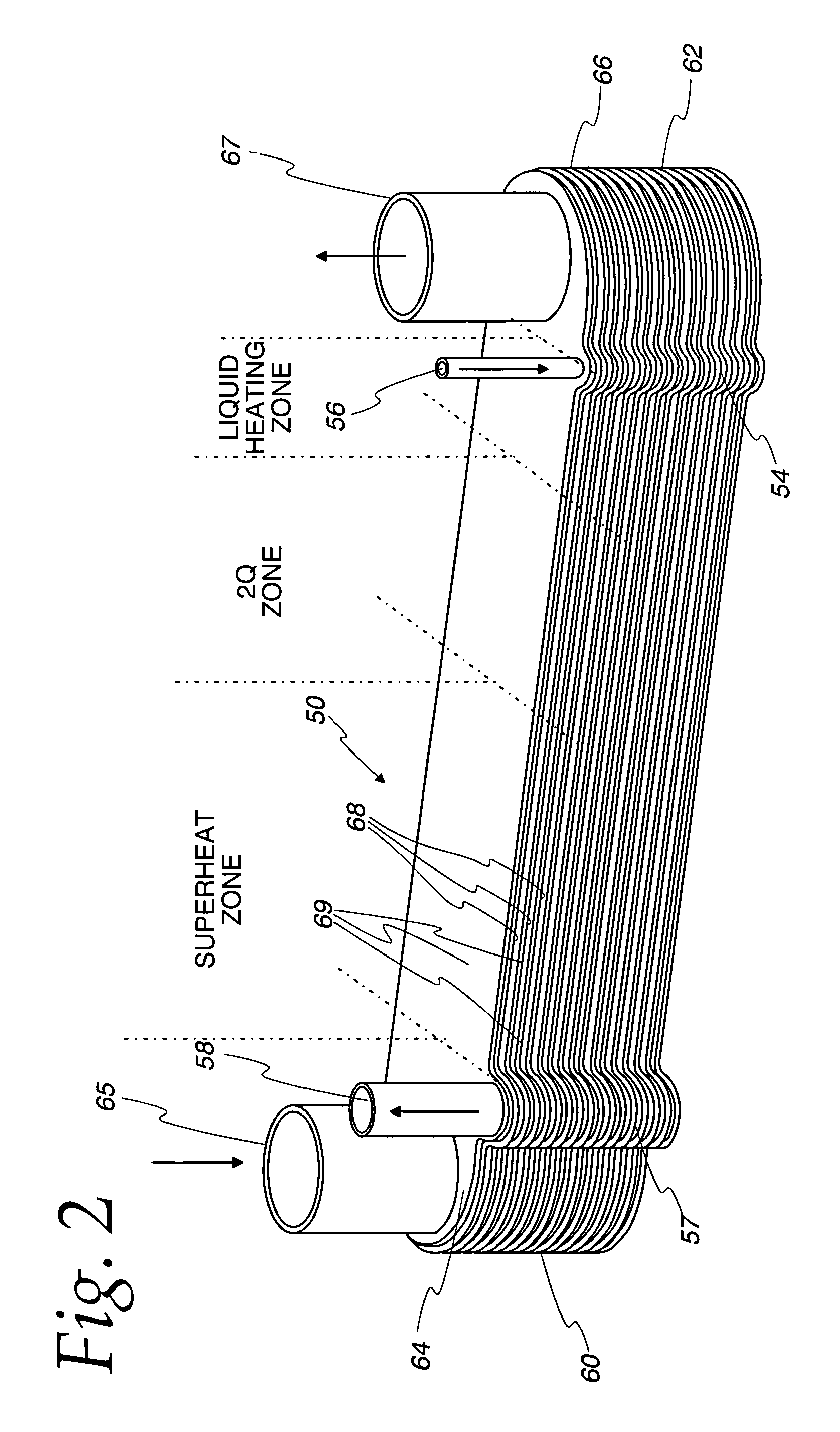
[0030]The present invention will be described in the context of use in a reformer type fuel cell system. However, the vaporizer of the invention is not limited to use in such systems or to the vaporization of fuel. It can be employed with efficacy in any context requiring a vaporizer operating with relatively high temperature differentials and which superheats the vaporized material to minimize thermal stress in that part of the vaporizer wherein the material being vaporized is superheated. Thus, no restriction to fuel cells or the vaporizing of fuel is intended except to the extent set forth in the appended claims.

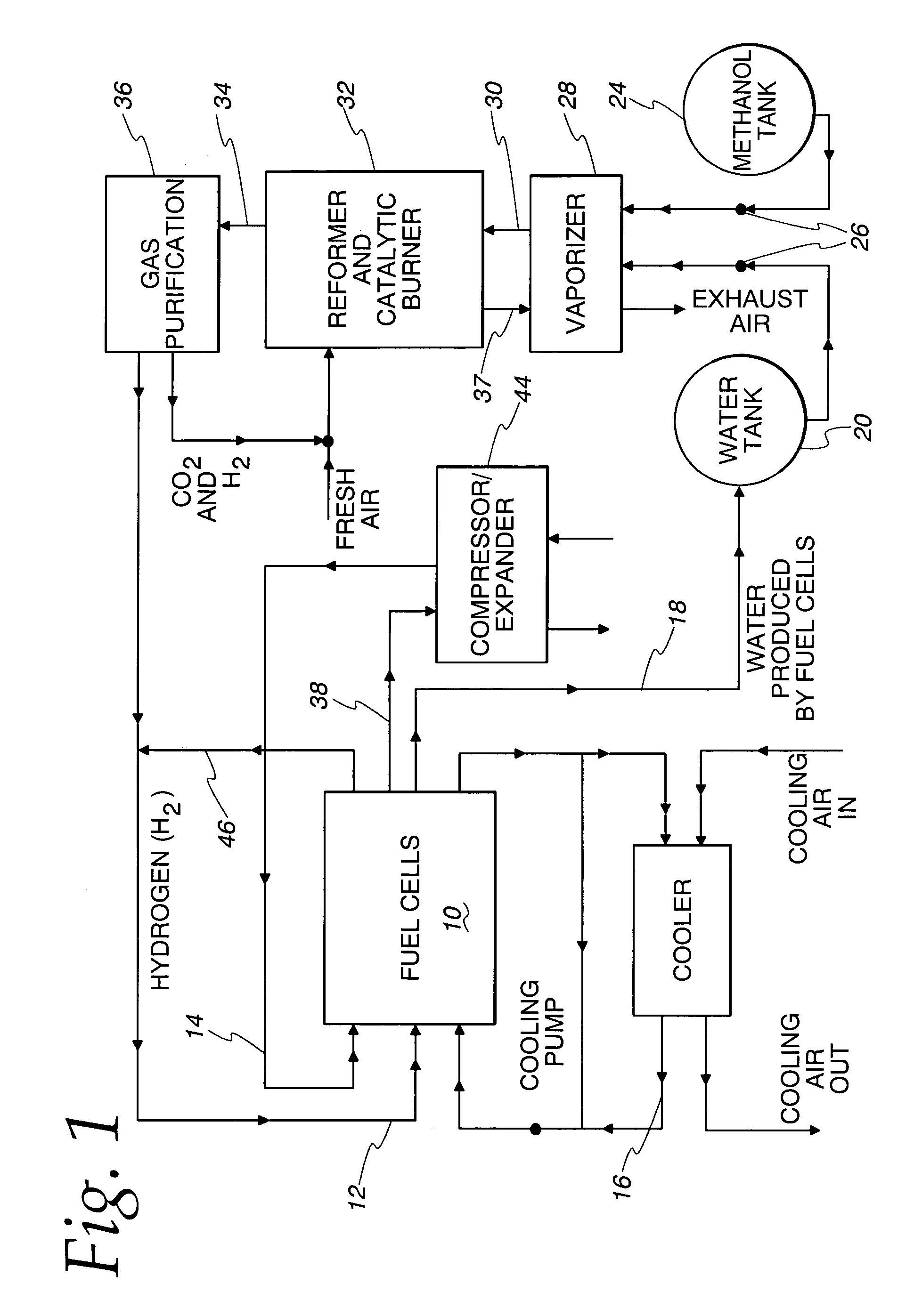
[0031]Turning now to FIG. 1, one type of fuel cell system embodying a reformer with which the invention may be used is illustrated in FIG. 1. This system is specifically intended to be employed in a vehicle but may be used to advantage in other environments.

[0032]The system includes a fuel cell 10 with provision for an anode gas inlet stream on a line 12. The anode gas ty...


PUM

PropertyMeasurementUnit
lengthaaaaaaaaaa
distanceaaaaaaaaaa
heat transfer enhancementaaaaaaaaaa

Abstract

Large thermal stresses are avoided and the fuel charge reduced in a vaporizer particularly suited for use in a reformer type fuel cell system and having a construction that includes alternating fuel / water flow path defining cells (68) and hot gas flow path cells (69) by providing heat transfer augmentation, such as a lanced and offset fin (120), only in that part of the gas flow path structure (69) adjacent the regions in the fuel / water flow path cells (68) where heating of the liquid fuel / water and vaporizing of the fuel / water where the mixture exists is a two phase material occurs and not in the area adjacent those parts of the fuel / water flow path structure (68) in which superheating of the vaporized fuel / water mixture is occurring.

Description

FIELD OF THE INVENTION[0001]This invention relates to vaporizers and, more particularly, to vaporizers of the type that bring a hot heat exchange fluid into heat transfer relation with a liquid that is to be fully evaporated to a super heated vapor.BACKGROUND OF THE INVENTION[0002]There are many applications for vaporizers of various sorts. In the broadest sense, a vaporizer converts a liquid to a vapor or a two phase mixture of liquid and vapor, or may convert a two phase mixture of vapor and liquid to a wholly, single phase vapor. In some instances, vaporizers may also provide a conversion from the solid phase to the liquid phase en route to providing a vapor or a two phase liquid / vapor mixture.[0003]In some vaporizers, the material to be vaporized is brought into contact with a hot surface that may be heated by a nonfluid medium as, for example, an electrical heating element or by radiation impinging upon the heating surface. In most other cases, however, the vaporization occurs ...

Claims


Application Information

Patent Timeline
Patent Type & Authority Patents(United States)
IPC IPC(8): F28F3/08F28D9/00F28F13/06H01M8/04H01M8/06
CPCF28D9/005H01M8/0631F28F13/06F28D2021/0043Y02E60/50H01M8/04007F28D9/0037F28D9/0043F28F3/06H01M8/06F28D9/00F28F3/00
Inventor REINKE, MICHAEL J.VALENSA, JEROEN
Owner MODINE MFG CO
Why Eureka
Try Eureka