Automated geo-fence boundary configuration and activation

a geo-fence and automatic technology, applied in the field of location tracking, can solve the problems of requiring a user, failing to provide any mechanism for detecting the movement of the asset from an arbitrary current location, and existing techniques often fail to provide sufficient precision to detect small movements of the asset, so as to improve the response time, reduce the possibility of user error in specifying the geo-fence, and improve the reliability

Active Publication Date: 2011-09-13
GORDONHOWARD ASSOC INC
View PDF85 Cites 148 Cited by
  • Summary
  • Abstract
  • Description
  • Claims
  • Application Information

AI Technical Summary

Benefits of technology

[0019]In yet another embodiment, the geo-fence can be activated and / or deactivated without the use of an onboard device at the vehicle. The driver (or other individual) can activate a geo-fence by direct communication with a central server, either by logging on to a web page, or by telephone call, SMS text message, instant message, or by some other means. Upon receiving such an activation message or communication, the central server establishes and activates a geo-fence around the vehicle based on its current position. Upon receiving a deactivation message or communication, the central server deactivates the geo-fence. In this manner, a driver or other individual can control, activate, deactivate, and configure the geo-fence even when he or she is not at the same physical location as the vehicle.
[0020]By establishing a geo-fence based on current asset position, the present invention provides much greater reliability as compared with prior art systems. The possibility of user error in specifying the geo-fence is reduced, since the geo-fence boundary is automatically determined rather than manually entered. Geo-fences can be established with much finer granularity, since there is no need to encompass an entire parking lot or other location defined in terms of an address; thus small movements of the asset can be detected and response time can be improved. In addition, the present invention provides mechanisms for passively initiating a geo-fence, for example when a vehicle has been parked or under other conditions, with a minimum of burden on the user / driver.

Problems solved by technology

A limitation inherent in many currently available GPS monitoring systems is that they require a user to specify the geo-fence boundary settings, for example by drawing a perimeter on a map.
One limitation of such techniques is that they fail to provide any mechanism for detecting movement of the asset from an arbitrary current location, unless the current location is manually specified by the user.
In addition, whether the geo-fence is specified based on a point location or by drawing a perimeter on a map, existing techniques often fail to provide sufficient precision to detect small movements of the asset; in other words, no boundary violation is detected until the asset has moved outside the geo-fence, which may be a undesirably large area because of the inability to manually specify a small area immediately surrounding the asset.
It may not be feasible or possible to specify the geo-fence specifically or with a fine level of detail, since a) the correlation between address and GPS position may be imperfect, and b) the address may correspond to a large parking lot (such as at an airport), and the user may have no way of knowing where, specifically and within the parking lot, the vehicle is to be parked.
Thus, the geo-fence configured by the user may be relatively large.
As a consequence, small movements of the vehicle (such as those that remain within the coarse definition of the geo-fence) may go undetected.
Such limitations can reduce reliability of the system and impair prompt response to events such as vehicle theft.
In addition, current techniques are subject to error, since the user may specify the geo-fence incorrectly.
Such error can result in false positives as well as the possibility that theft may go undetected.
Furthermore, existing techniques do not provide any automated means for activating location notification automatically or passively under certain conditions, using a geo-fence derived from a current location of the asset.
Existing techniques do not provide any mechanism for automatically determining the location of a remote asset and establishing a geo-fence or other boundary surrounding the asset based on its current location.
Accordingly, existing location tracking techniques are of limited use in detecting movement of assets and of reliably notifying owners and other parties of asset movement.

Method used


Image

  • Automated geo-fence boundary configuration and activation
  • Automated geo-fence boundary configuration and activation
  • Automated geo-fence boundary configuration and activation

Examples


Embodiment Construction

[0026]In one embodiment, the present invention includes or interfaces with location tracking functionality as described in related to U.S. patent application Ser. No. 11 / 539,292 for “STARTER-INTERRUPT DEVICE INCORPORATING GLOBAL POSITIONING SYSTEM FUNCTIONALITY”, filed Oct. 6, 2006, the disclosure of which is incorporated herein by reference. One skilled in the art will recognize that the present invention can be implemented with or without such location tracking functionality.

[0027]For illustrative purposes, the description provided herein sets forth the invention in the context of vehicles. However, one skilled in the art will recognize that the invention can be used in connection with any product.

[0028]For purposes of the following description, “vehicle owner”, “owner”, and “user” are synonymous and can refer to any individual who is interacting with the components of the present invention.

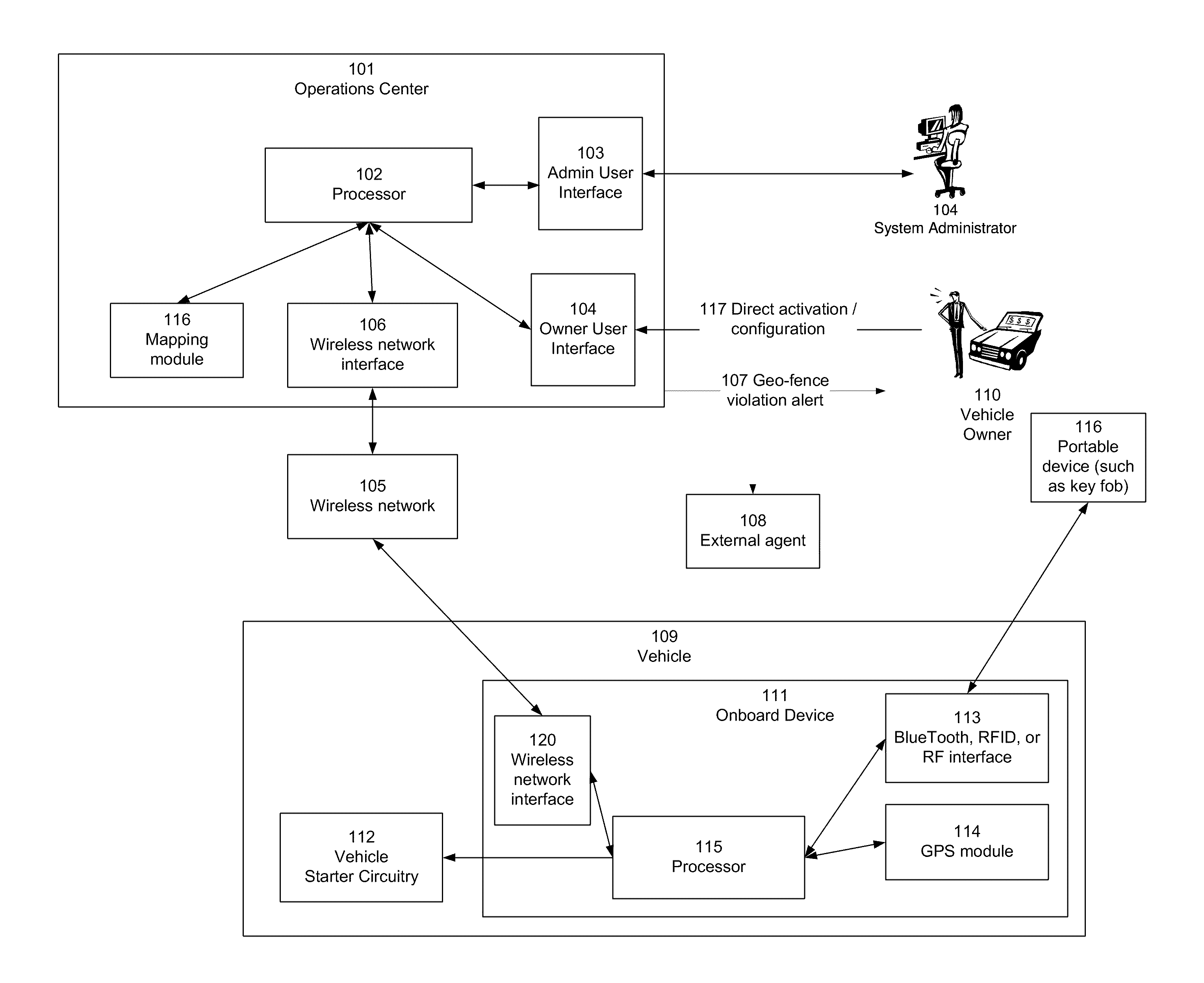
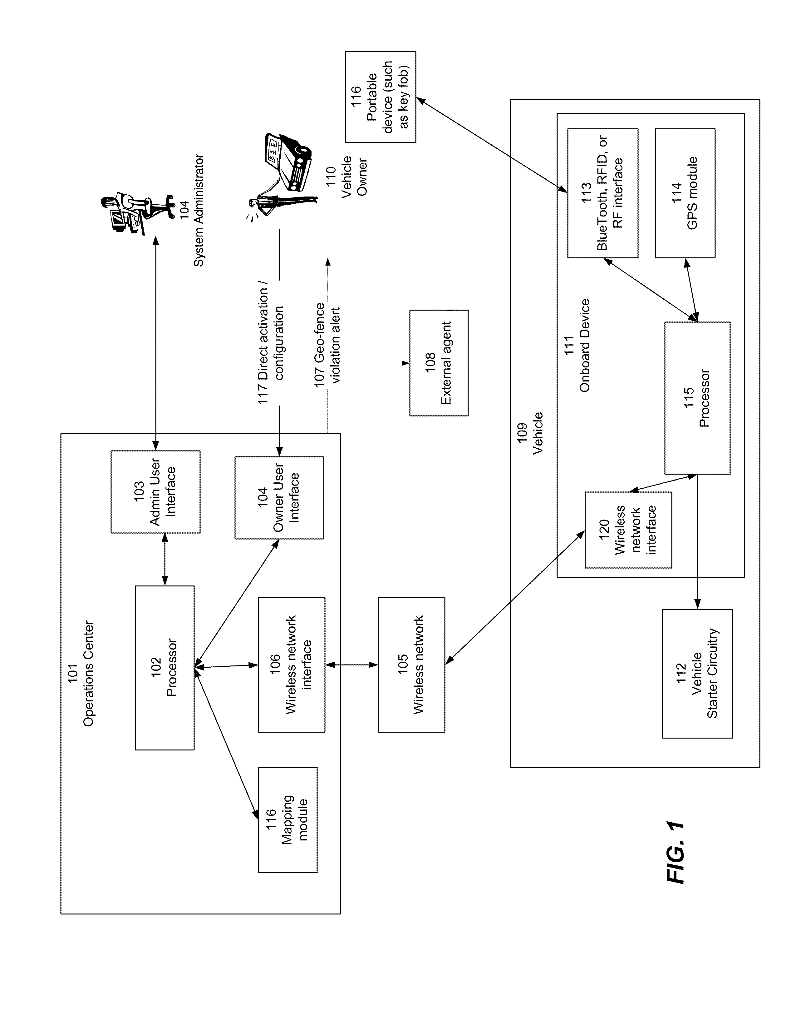
[0029]Referring now to FIG. 1, there is shown a block diagram depicting an overall architec...


PUM


Abstract

A geo-fence is defined and established automatically based on a current location of an asset along with some range or distance, avoiding the need for a user to manually specify a location by drawing a perimeter, specifying a point location, or by any other means. Once established, the geo-fence can be activated so as to notify the owner of the asset and / or some other entity of movement of the asset beyond the boundary specified by the geo-fence. In one embodiment, the geo-fence can be automatically activated upon certain conditions, or can be manually activated, or any combination thereof.

Description

CROSS-REFERENCE TO RELATED APPLICATION[0001]This invention is related to U.S. patent application Ser. No. 11 / 539,292 for “STARTER-INTERRUPT DEVICE INCORPORATING GLOBAL POSITIONING SYSTEM FUNCTIONALITY”, filed Oct. 6, 2006, the disclosure of which is incorporated herein by reference.FIELD OF THE INVENTION[0002]The present invention relates to location tracking, and more specifically to techniques for specifying and activating a location perimeter (referred to as a geo-fence), and detecting a boundary violation with respect to the specified perimeter.DESCRIPTION OF THE RELATED ART[0003]Location tracking is a useful mechanism for limiting or preventing theft of assets such as vehicles, and for recovering stolen assets. Various location tracking mechanisms are well known in the art. For example, Global Positioning System (GPS) functionality is a well-known and ubiquitous technique for tracking a vehicle's location. In addition, other mechanisms are known, such as triangulation by cellul...

Claims


Application Information

Patent Timeline
Patent Type & Authority Patents(United States)
IPC IPC(8): B60R25/10B60R25/04
CPCB60R25/04B60R25/102B60R25/33G01S5/0027G06Q10/06G06Q10/08G06Q50/30G08G1/205H04W4/021H04W4/022B60R25/10G01S19/42H04W4/046
Inventor MORGAN, GERALD A.SCHWARZ, STANLEY G.
Owner GORDONHOWARD ASSOC INC
Why Eureka
Try Eureka