

AC generator for vehicle
A technology for alternators and vehicles, applied in electrical components, electromechanical devices, electric components, etc., can solve the problems of deterioration of electrical insulation and aggravation of thermal degradation, and achieve the effect of good heat dissipation and enlarged area
- Summary
- Abstract
- Description
- Claims
- Application Information
AI Technical Summary
Problems solved by technology
Method used
Image

Examples
Embodiment approach 1
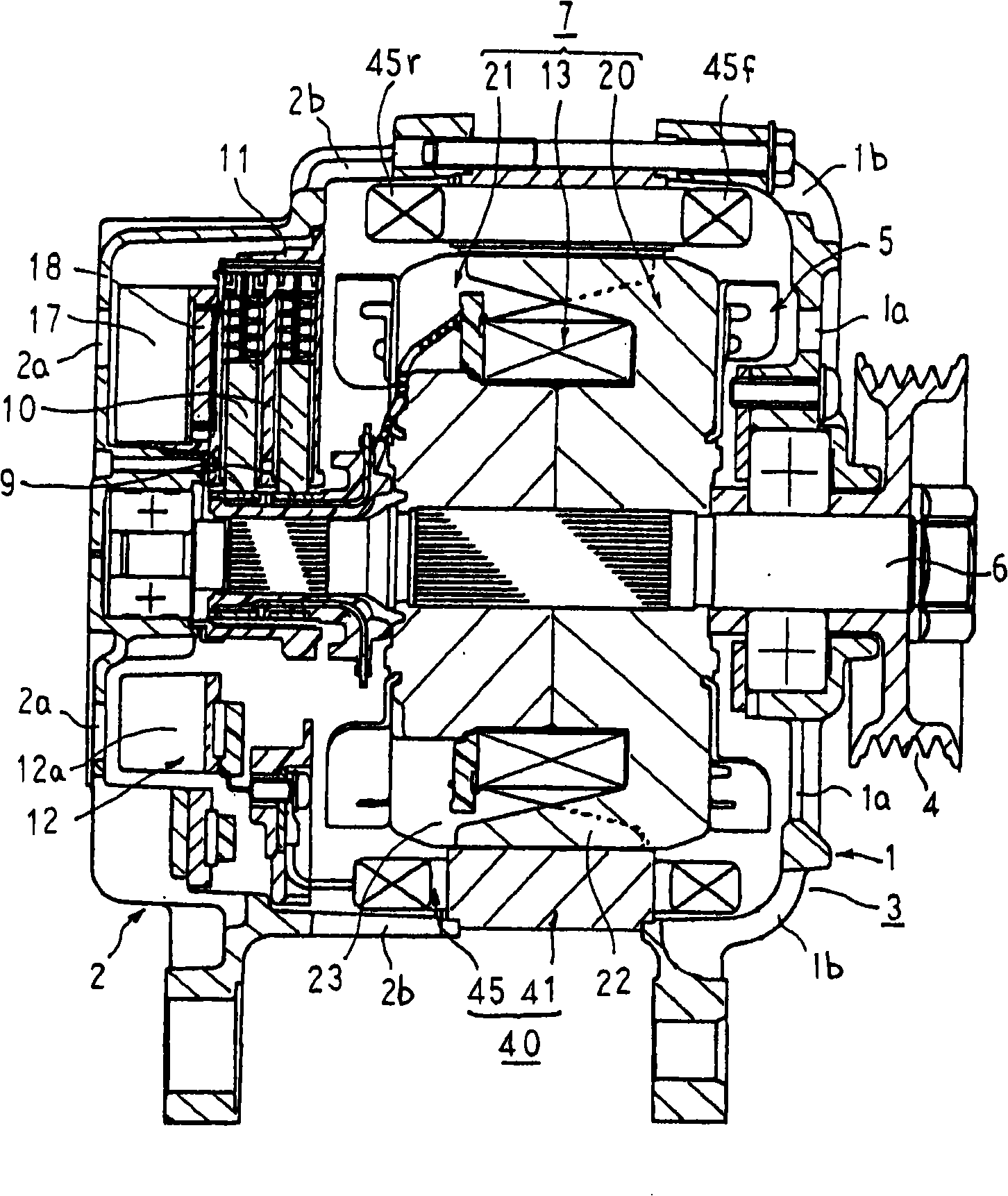
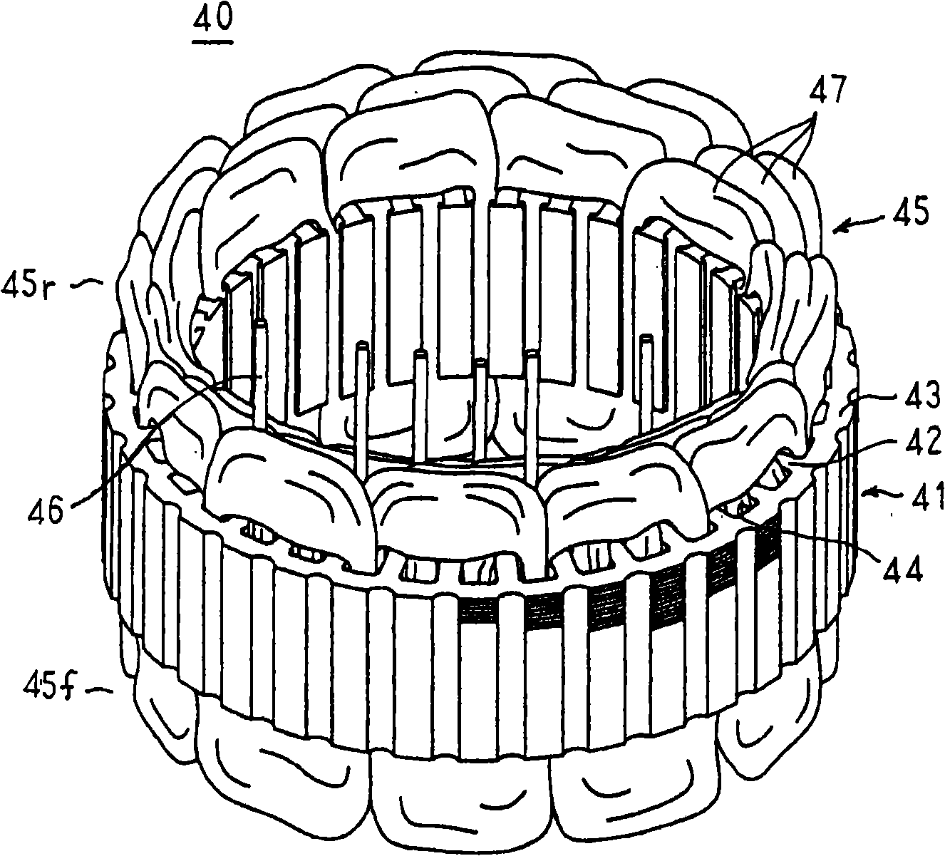
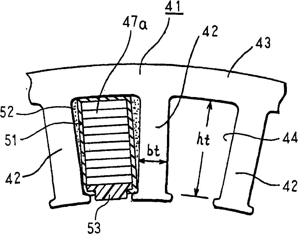
[0048] figure 1 is a sectional view showing the vehicle alternator according to Embodiment 1 of the present invention, figure 2 is a perspective view showing a stator of the vehicle alternator according to Embodiment 1 of the present invention, image 3 It is a partial cross-sectional view showing the slot-accommodated state of the stator winding in the stator of the vehicle alternator according to Embodiment 1 of the present invention, Figure 4 It is a main part side view showing the stator of the vehicle alternator according to Embodiment 1 of the present invention, Figure 5 It is a process drawing explaining the process of manufacturing the star winding unit in the manufacturing method of the stator of the automotive alternator which concerns on Embodiment 1 of this invention. Image 6 and Figure 7 are a perspective view and an enlarged view of main parts, respectively, showing a bisected winding unit in the stator of the vehicle alternator according to Embodiment 1...
Embodiment approach 2
[0084] Figure 10 is a perspective view showing a stator of a vehicle alternator according to Embodiment 2 of the present invention, Figure 11 It is a main part side view showing the stator of the vehicle alternator according to Embodiment 2 of the present invention, Figure 12 It is a partial cross-sectional view showing the slot-accommodated state of the stator winding in the stator of the vehicle alternator according to Embodiment 2 of the present invention, Figure 13 is a perspective view showing a single-phase winding in a stator of a vehicle alternator according to Embodiment 2 of the present invention, Figure 14 It is an enlarged view showing a main part of a single-phase winding in the stator of the vehicle alternator according to Embodiment 2 of the present invention.
[0085] Figure 10 to Figure 14 Among them, the stator 40A is composed of a stator core 41A and a stator winding 45A wound on the stator core 41A. The stator core 41A is produced in the same mann...
Embodiment approach 3
[0096] Embodiment 3 such as Figure 15 As shown, the entire area in the axial direction of the blade 5 a of the cooling fan 5 substantially overlaps the coil end groups 45 f and 45 r in the radial direction. In addition, other configurations are the same as those of Embodiment 2 described above.
[0097] According to the third embodiment, since the entire axial area of the blade 5a of the cooling fan 5 substantially overlaps the coil end groups 45f and 45r in the radial direction, the cooling fan 5 can reliably supply cooling air to the coil end groups 45f and 45r. , thereby improving the cooling performance of the coil end groups 45f and 45r. Furthermore, since the discharge side of the cooling fan 5 is shielded by the coil end groups 45f and 45r, an effect of shielding the diffusion of noise can be produced, thereby reducing wind noise.
[0098] In addition, in the above-mentioned embodiments, the cases where the number of slots per pole and phase are 1 and 2 have been d...
PUM
 Abstract
Description
Claims
Application Information