Laser processing nozzle

A laser processing and nozzle technology, which is applied in laser welding equipment, metal processing equipment, manufacturing tools, etc., can solve problems such as hindering the formation of plasma, and achieve the effect of improving the cutting effect

Inactive Publication Date: 2008-12-10
TRUMPF WERKZEUGMASCHINEN GMBH & CO KG
View PDF1 Cites 0 Cited by
  • Summary
  • Abstract
  • Description
  • Claims
  • Application Information

AI Technical Summary

Problems solved by technology

Plasma formation must be hindered especially when cutting thick sheets

Method used


Image

  • Laser processing nozzle
  • Laser processing nozzle
  • Laser processing nozzle

Examples


Embodiment Construction

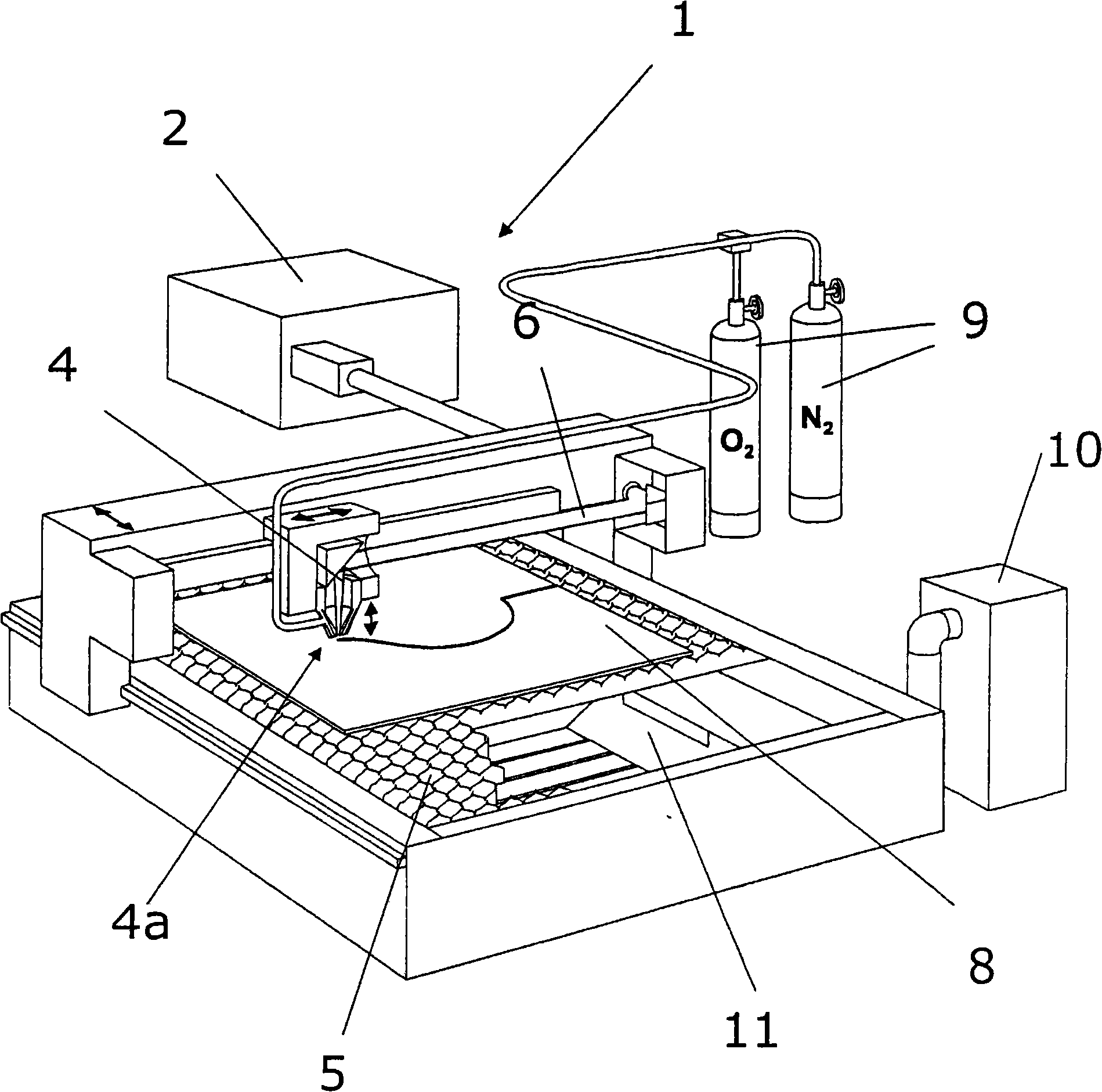
[0022] attached figure 1 Shows the structure of a laser processing device 1 for laser cutting, with a CO 2 Laser 2 , a laser processing head 4 (laser processing nozzle 4 a ), and a workpiece support 5 . The generated laser beam 6 is directed towards the laser machining head 4 by means of deflection mirrors and directed towards the workpiece 8 by means of mirrors.

[0023] The laser beam 6 has to penetrate the workpiece 8 before forming a continuous cutting seam. The plate 8 must be melted or oxidized in spots at one point, and the melt must be blown away.

[0024] Piercing as well as laser cutting both require supplemental gas support. Oxygen, nitrogen, compressed air and / or special purpose gases can be used as cutting gas 9 . Which gas to use in the end depends on what material to cut and what quality requirements you have on the workpiece.

[0025] The generated plasma and gases can be sucked out of the suction chamber 11 by means of the suction device 10 .

[0026] ac...


PUM


Abstract

A laser machining nozzle (4a) having at least one supply chamber (14) for the laser beam and for a machining gas comprises a cavity (17), which is located in the area of the opening (15) of the gas supply chamber (14) and which is open toward the workpiece to be machined, this opening having a wedge-shaped edge (18').

Description

technical field [0001] The invention relates to a laser processing nozzle having at least one feed chamber for a laser beam and for a processing gas. Background technique [0002] A laser machining nozzle of this type is known, for example, from US 6,423,928 B1. [0003] According to the prior art, during fusion cutting (for example VA steel), the aperture diameter of laser processing nozzles designed as aperture nozzles should be increased as the thickness of the sheet to be processed increases. This requires greater gas pressure. Increasing the gas pressure, however, means increasing the gas density in the cutting gap, whereby plasma formation is more likely. The plasma threshold is also related to the incident power density (high power density or process temperature >> plasma) and focus position (high focus position >> plasma) and limits the quality of fusion. [0004] When cutting thick plates, reducing the cutting air pressure can obtain better cutting ed...

Claims


Application Information

Patent Timeline
Patent Type & Authority Applications(China)
IPC IPC(8): B23K26/14B23K26/38
CPCB23K26/04B23K26/1435B23K26/1464B23K26/38B23K26/1438
Inventor N·斯佩克
Owner TRUMPF WERKZEUGMASCHINEN GMBH & CO KG
Why Eureka
Try Eureka