Outdoor equipment for load driving apparatus and air conditioner, and load driving method

A technology of load driving and driving method, which is applied in the direction of AC motor control, refrigerator, heating method, etc., can solve problems such as inappropriate power supply

Active Publication Date: 2009-03-25
DAIKIN IND LTD
View PDF7 Cites 12 Cited by
  • Summary
  • Abstract
  • Description
  • Claims
  • Application Information

AI Technical Summary

Problems solved by technology

Thus, in Image 6 , Figure 7 In the illustrated technology, it is not appropriate to omit step S16 and only use step S17 to cut off the power supply of compressor driver 31a and fan driver 31b

Method used


Image

  • Outdoor equipment for load driving apparatus and air conditioner, and load driving method
  • Outdoor equipment for load driving apparatus and air conditioner, and load driving method
  • Outdoor equipment for load driving apparatus and air conditioner, and load driving method

Examples


Embodiment Construction

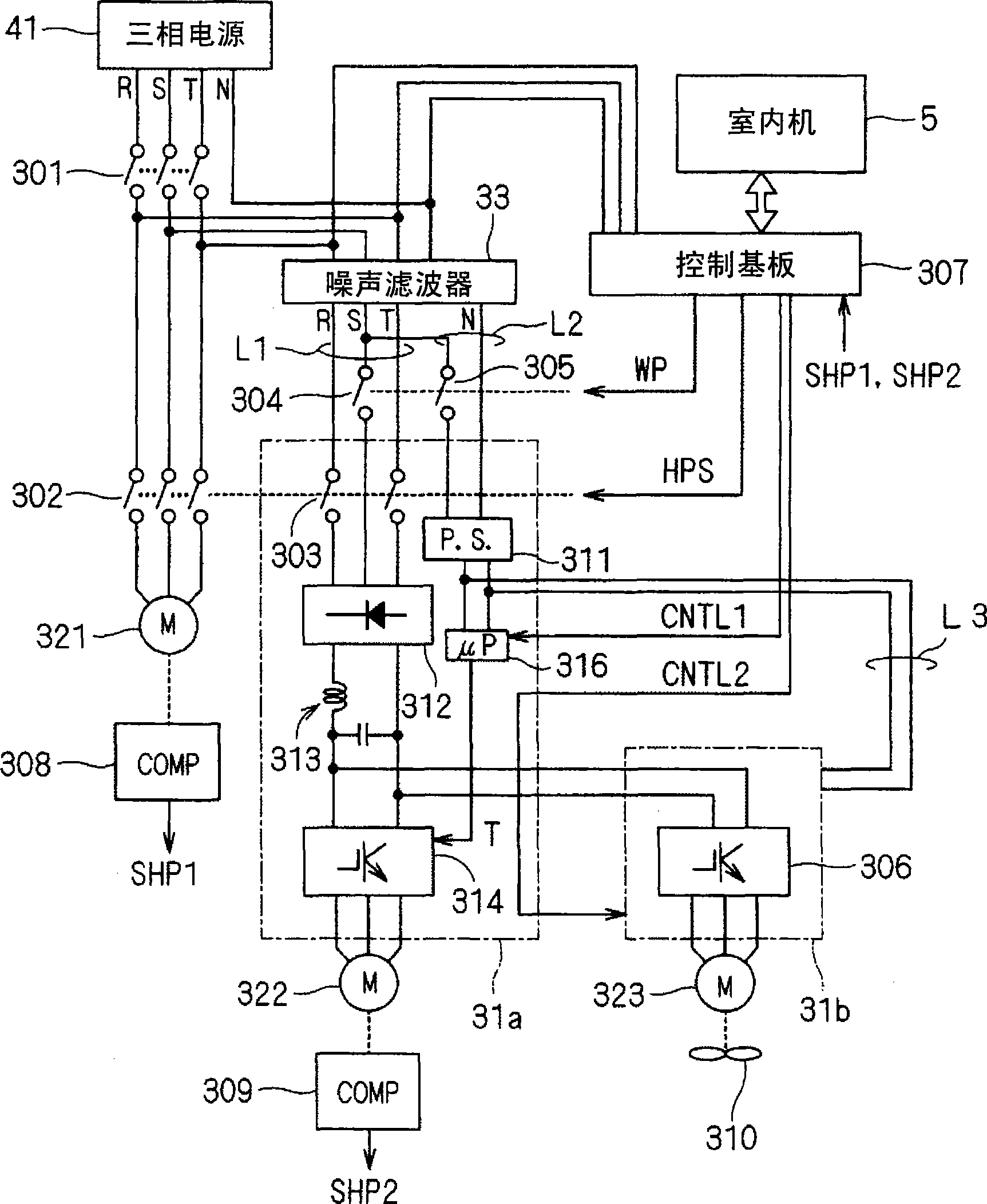
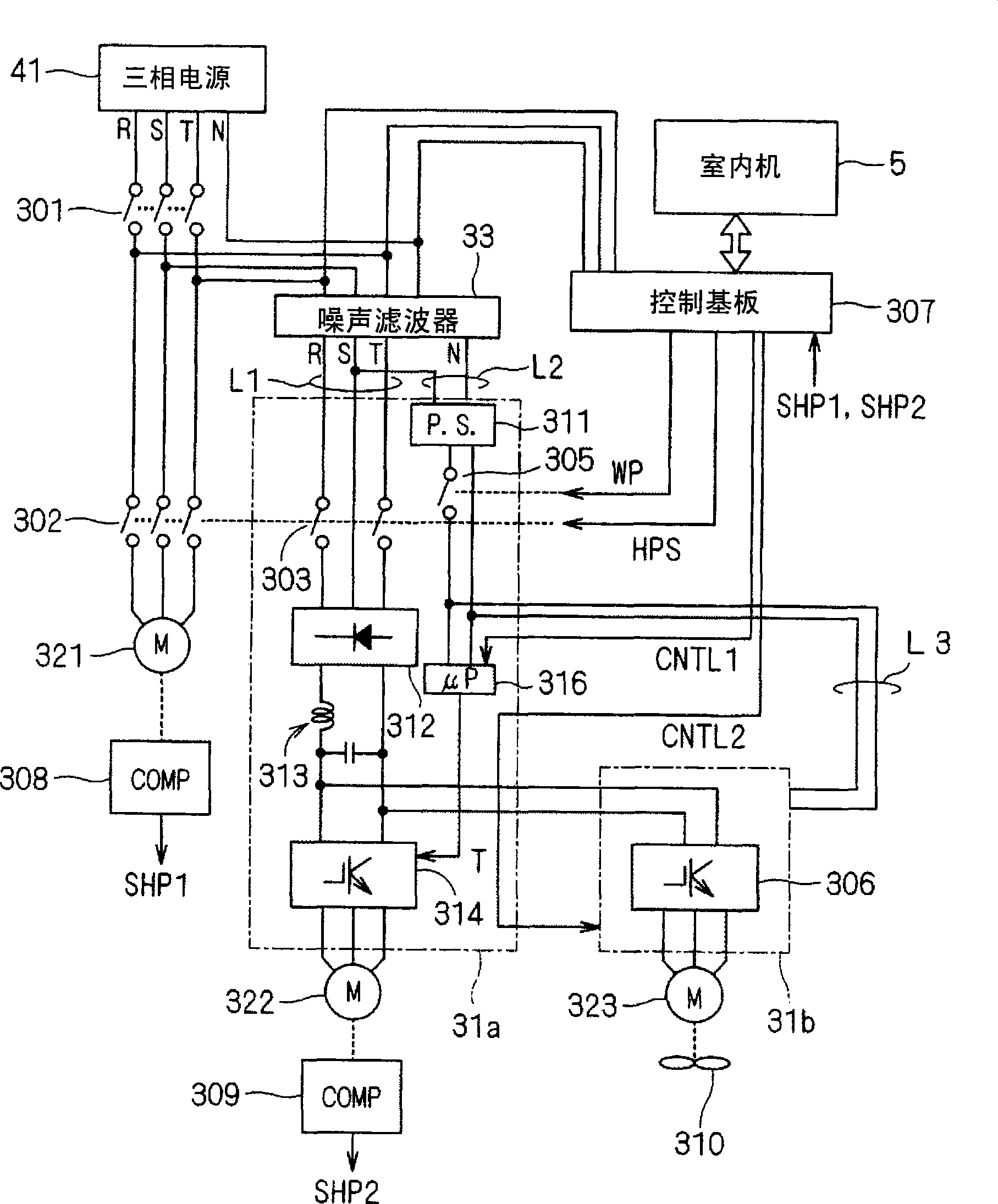
[0068] figure 1 It is a circuit diagram illustrating the configuration of an embodiment of the present invention. exist Figure 6 The structure shown and figure 1 In the shown structure, the same code|symbol is attached|subjected to the same component.

[0069] and Figure 6 The main difference of the shown structure is that: the control switch 305 connected to the output side of the power switch 301 and turned on / off by the switching command WP is provided; and the switching command WP is output from the control board 307 .

[0070] More specifically, the control switch 305 is located between the noise filter 33 and the power input 311 of the compressor driver 31a, and supplies / shuts off electric power to the compressor driver 31a.

[0071] In this embodiment, as the power line group L2 connected to the power supply input 311 in the compressor driver 31a, neutral point N and S-phase power lines are used, and the conduction of one S-phase power line in the power line group...


PUM


Abstract

Power saving is implemented by cutting power to a compressor driver (31a) and a fan driver (31b) while operating power is kept supplied to a control substrate (307). After the power source to the control substrate (307) is turned on, power is supplied to the compressor driver (31a) and the fan driver (31b). Then, when it is determined that an indoor unit is in operation, the compressor driver (31a) and the fan driver (31b) are operated. Meanwhile, when it is determined that the indoor unit is not in operation, after the lapse of ten minutes or twenty minutes under a predetermined setting, the power to the compressor driver (31a) and the fan driver (31b) is cut. When the operation of the indoor unit is started again, power is supplied to the compressor driver (31a) and the fan driver (31b).

Description

technical field [0001] The present invention relates to a technology for driving a load, for example, it can be applied to a technology for driving a compressor of an outdoor unit of an air conditioner. Background technique [0002] Conventionally, when driving a load such as a compressor of an outdoor unit of an air conditioner, an inverter may be used in order to control the driving. In addition, from the requirements of power saving, improvements were made to reduce standby power. As documents related to the present application, there are Patent Documents 1 to 5, for example. [0003] Patent Document 1: Japanese Patent Laid-Open No. 11-211253 [0004] Patent Document 2: Japanese Patent Laid-Open No. 11-311436 [0005] Patent Document 3: Japanese Patent Laid-Open No. 2000-205627 [0006] Patent Document 4: Japanese Patent Laid-Open No. 2000-333365 [0007] Patent Document 5: Japanese Patent Laid-Open No. 2000-346425 [0008] Figure 6 It is a circuit diagram showing ...

Claims


Application Information

Patent Timeline
Patent Type & Authority Applications(China)
IPC IPC(8): F24F11/02F24F11/33F24F11/38F24F11/47F24F11/49F24F11/61F24F11/62F24F11/64F24F11/72F24F11/86F24F11/88F24F11/89
CPCY02B30/741F24F2011/0075F25B49/025F25B2600/021F25B2600/11F24F11/006F25B2400/075F24F11/30F24F11/62F24F11/46Y02B30/70H02P27/06F24F2140/60
Inventor 夏目守邦八木达小谷拓也宫马保明猿渡博孝松浦弘幸林万里央
Owner DAIKIN IND LTD
Why Eureka
Try Eureka