Optical fiber drawing furnace

A technology of drawing furnace and optical fiber, which is applied in glass manufacturing equipment, manufacturing tools, etc., can solve the problems of the influence of the outer diameter of the optical fiber and the turbulent airflow, and achieve the effect of saving electricity and improving heating efficiency.

Active Publication Date: 2014-08-13
SUMITOMO ELECTRIC IND LTD
View PDF4 Cites 9 Cited by
  • Summary
  • Abstract
  • Description
  • Claims
  • Application Information

AI Technical Summary

Problems solved by technology

[0004] If the gas flow in the furnace tube is disturbed near the lower end of the glass base material in a heated and molten state, it may affect the outer diameter of the optical fiber, etc.

Method used


Image

  • Optical fiber drawing furnace
  • Optical fiber drawing furnace
  • Optical fiber drawing furnace

Examples


Embodiment Construction

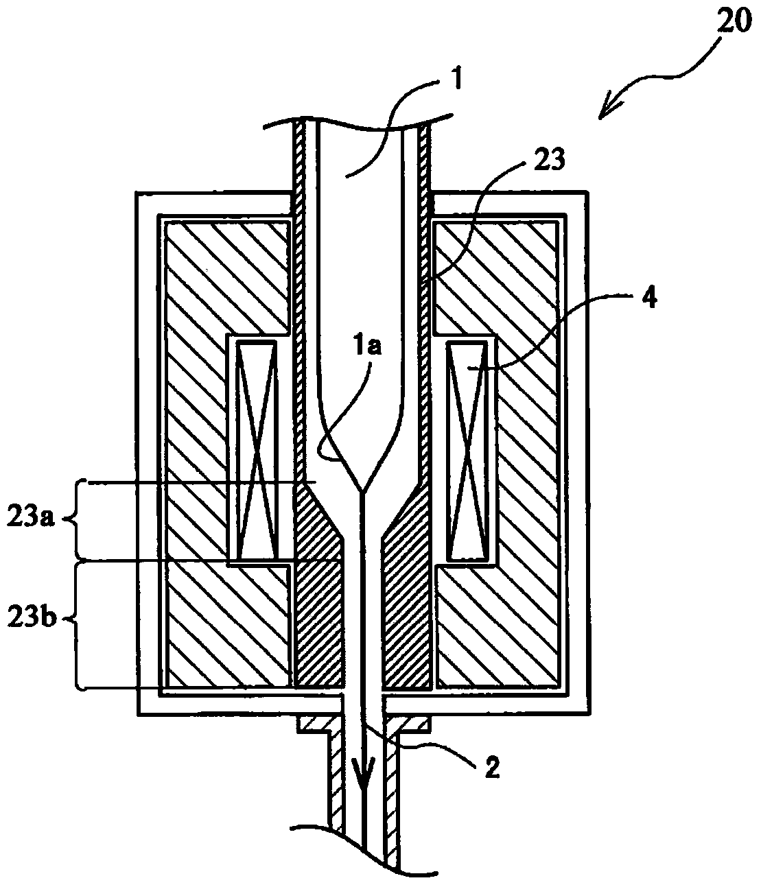
[0013] figure 2 It is a conceptual diagram showing the drawing furnace 20 disclosed in patent document 1. The drawing furnace 20 has a furnace tube 23 and a heater 4 for heating the furnace tube, and the optical fiber 2 is drawn by inserting the glass preform 1 for an optical fiber into the furnace tube 23 and heating and melting it. The optical fiber 2 hangs down from the lower end 1 a of the molten glass preform located in the center of the heater 4 and is drawn out downward. The furnace core tube 23 has: a reduced-diameter part 23a whose inner diameter is tapered along the shape of the lower end part 1a of the glass base material; and a reduced-diameter tube part 23b whose uniform inner diameter and outer diameter Unreduced uniform outer diameter.

[0014] According to the drawing furnace 20, the inert gas flow in the furnace core tube 23 can be formed into a laminar flow, and fluctuations in the outer diameter of the optical fiber can be suppressed. According to the wi...


PUM


Abstract

The invention provides an optical fiber drawing furnace which performs optical fiber drawing by using a core tube having a necked part corresponding to a heated and melted lower end part of a glass base material, and is capable of increasing the heating efficiency of the glass base material and thereby saving power. A drawing furnace (10) includes in a furnace frame (16): a core tube (13); a heating device (14) for heating the core tube; and a first heat insulating material (15a) encapsulating the outside of the core tube. The drawing furnace is used for plugging an optical fiber used glass base material (11) into the core tube for heating and melting, and drawing optical fibers (12). The core tube (13) includes a necked part (13a), wherein the inner diameter of the necked part decreases from the central part of the heating device (14) towards the lower end, forming a taper shape; and a necked tube part (13b) arranged under the heating device (14), wherein the outer diameter is also reduced. A second insulating material (15b) for suppressing heat dissipation is arranged in a space formed between the necked tube part and the first heat insulating material in the furnace frame.

Description

technical field [0001] The invention relates to an optical fiber drawing furnace which heats and melts a glass parent material for an optical fiber and draws an optical fiber. Background technique [0002] The optical fiber drawing furnace is composed of: a furnace core tube is arranged in the furnace frame, and the glass base material for optical fiber (hereinafter referred to as the glass base material) is inserted into the furnace core tube; heating; and a heat insulating material, which surrounds the furnace core tube and the heating device from the outside, and suppresses the release of heat to the outside. Carbon with high thermal conductivity made of isotropic graphite or the like is used for the furnace core tube, and porous carbon is used as the heat insulating material in order to enhance the heat insulating effect. The furnace frame is made of corrosion-resistant metal and has a water-cooled structure. [0003] In order to prevent the furnace core tube from oxid...

Claims


Application Information

Patent Timeline
Patent Type & Authority Applications(China)
IPC IPC(8): C03B37/029
Inventor 冈崎岩山崎卓小西达也
Owner SUMITOMO ELECTRIC IND LTD
Why Eureka
Try Eureka