Structure of front portion of vehicle body

a technology of front portion and vehicle body, which is applied in the direction of roofs, bumpers, vehicular safety arrangments, etc., can solve the problems of difficult to reduce the gap between the air duct portion and the front exterior member, and achieve the effect of enhancing the cooling efficiency of the heat exchanger

Inactive Publication Date: 2006-10-03
CALSONIC KANSEI CORP
View PDF15 Cites 52 Cited by
  • Summary
  • Abstract
  • Description
  • Claims
  • Application Information

AI Technical Summary

Benefits of technology

[0010]According to the first aspect of the invention, the seal portion forms a seal between the front end of each air guide plates and the front exterior member. Therefore, hot air leaking from the inside of an engine room, is positively prevented from being drawn into the air duct portion after it flows around the front end of the air guide plate. As a result, the cooling efficiency of a heat exchanger can be enhanced.

Problems solved by technology

The air duct portion is made of a relatively hard synthetic resin, and therefore it is difficult to reduce a gap between the air duct portion and a front exterior member (such as a bumper fascia and a radiator grille), provided on the front side of this air duct portion, to zero.

Method used


Image

  • Structure of front portion of vehicle body
  • Structure of front portion of vehicle body
  • Structure of front portion of vehicle body

Examples


Embodiment Construction

[0026]Referring now to the accompanying drawings, there is shown a preferred embodiment of the invention.

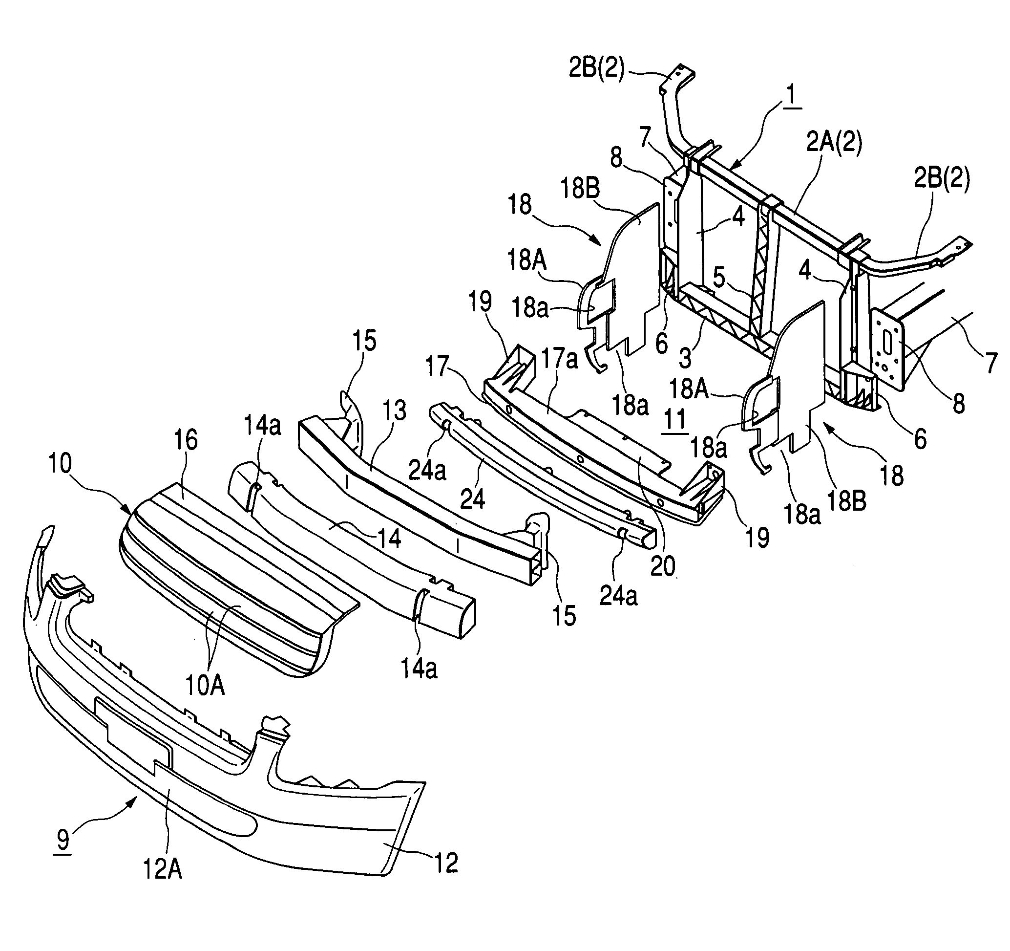
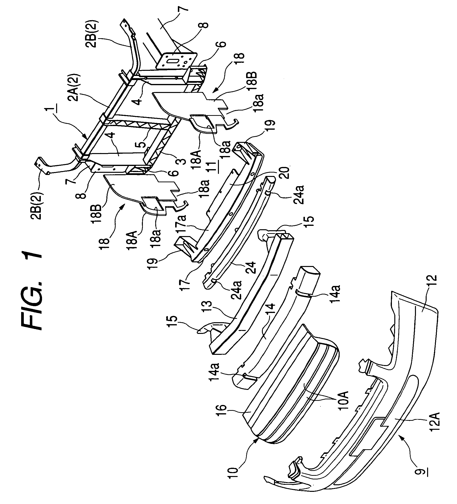
[0027]In FIG. 1, reference numeral 1 denotes a radiator core support member 1 for mounting and supporting a heat exchanger, such as a condenser and a radiator, thereon. The support member 1 includes an upper member 2, a lower member 3, side stay portions 4 provided respectively at opposite (right and left) side portions of the support member 1, and a hood lock stay 5 provided at a central portion of the support member 1. The side stay portions 4 and the hood lock stay 5 interconnect the upper member 2 and lower member 3.

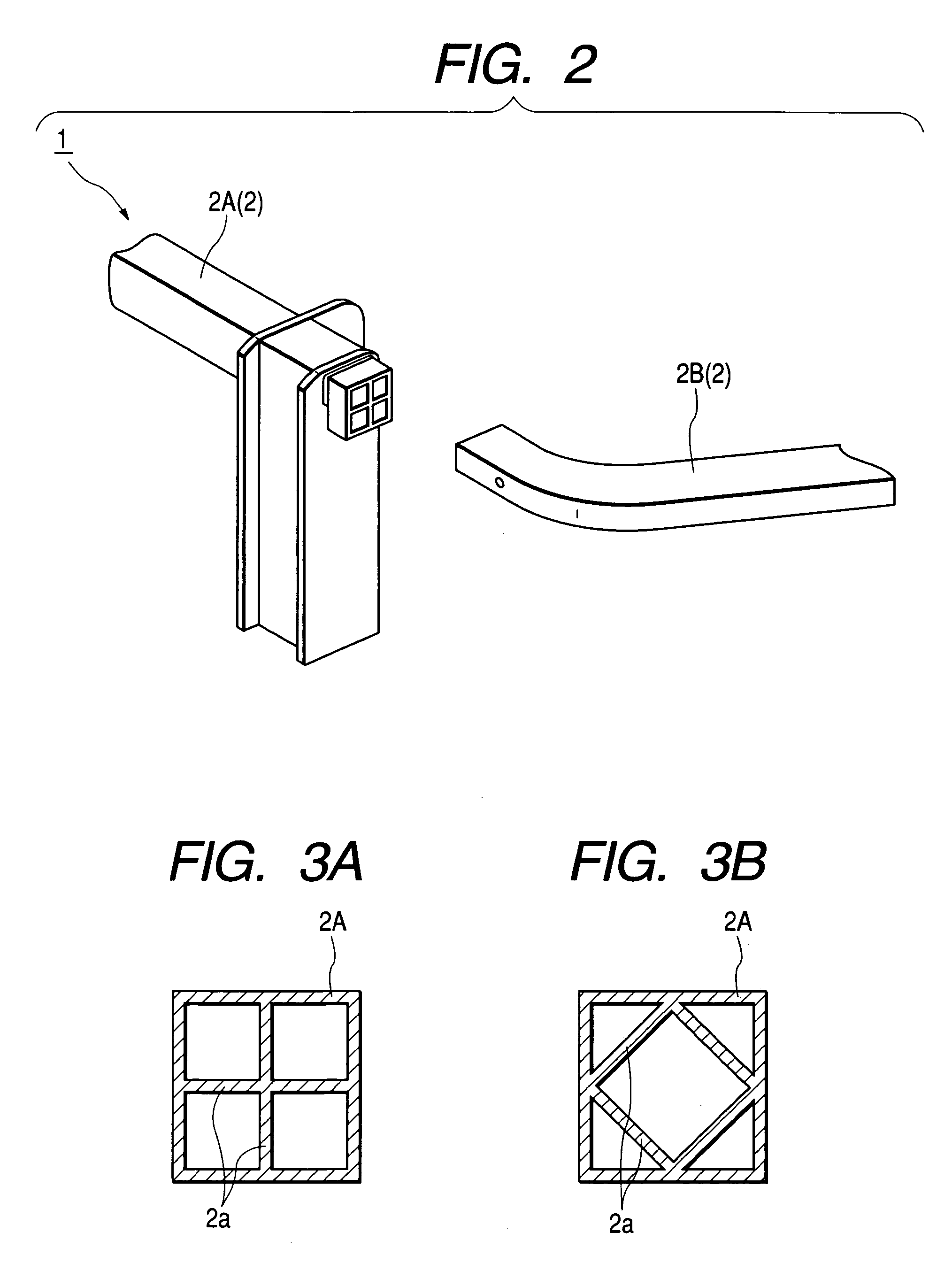
[0028]In a first embodiment, the upper member 2 is divided into a center portion 2A and two opposite side portions 2B. Each of the center portion 2A and the side portions 2B is made of light metal such as aluminum. For example, the center portion 2A is extruded to have a rectangular cross-section, and the side portions 2B are fitted and fixedly secured by welding ...


PUM


Abstract

A portion between a front end of an air guide plates, which forms an air duct portion, and the front exterior member of the vehicle is sealed by a seal portion. Therefore, hot air leaking from inside of an engine room, is positively prevented from being drawn into the air duct portion after it flows around the front end of the air guide plate.

Description

[0001]The present disclosure relates to the subject matter contained in Japanese Patent Application No. 2002-109600 filed on Apr. 11, 2002, which is incorporated herein by reference in its entirety.BACKGROUND OF THE INVENTION[0002]1. [Field of the Invention][0003]This invention relates to a structure of a front portion of a vehicle body.[0004]2. [Description of the Related Art][0005]There is known a conventional front portion structure of a vehicle body (as disclosed in JP-A-2001-213352 and JP-A-2001-080371) in which a picture frame-like air duct portion is provided on a front side of a radiator core support member, and cooling air (outside air) can be fed to a heat exchanger of a condenser or a radiator portion through the air duct portion.[0006]The air duct portion is made of a relatively hard synthetic resin, and therefore it is difficult to reduce a gap between the air duct portion and a front exterior member (such as a bumper fascia and a radiator grille), provided on the front...

Claims


Application Information

Patent Timeline
Patent Type & Authority Patents(United States)
IPC IPC(8): B60K13/02B60K11/04B60R19/12B60R19/18B60R19/48B62D25/08B62D29/00
CPCB60K11/04B62D25/084B62D29/001B62D29/004B60R19/12B60R2019/1873
Inventor MORI, TAKESHITAKAGI, MINORU
Owner CALSONIC KANSEI CORP
Why Eureka
Try Eureka