Continuous annealing device

An annealing device and annealing technology, applied in furnaces, heat treatment equipment, heat treatment furnaces, etc., can solve the problems of ring wire rope deterioration, cost increase, and high cost, and achieve the effects of lightening operations, reducing costs, and preventing thermal deterioration

Inactive Publication Date: 2009-04-15
CHUGAI RO CO LTD
View PDF2 Cites 3 Cited by
  • Summary
  • Abstract
  • Description
  • Claims
  • Application Information

AI Technical Summary

Problems solved by technology

[0011] However, when the endless steel wire rope is circulated along the direction of the entrance and exit side of the annealing furnace as mentioned above, a long steel wire rope with a length at least twice the length of the annealing furnace is required, and its cost increases. Part of it is located in the annealing furnace, so there is still the problem of deterioration of the endless steel wire rope due to the high temperature in the annealing furnace
[0012] Moreover, in order to move the above-mentioned long looped wire rope circularly, a large power is required, resulting in an increase in operating cost. Moreover, a load acts on the looped wire rope during movement, and there is a problem that the looped wire rope is easily broken.
[0013] In addition, if the furnace length of the annealing furnace is increased as mentioned above, it is necessary to circulate the steel wire rope with more than double the length. Not only the cost is very high, but also it is difficult to circulate the endless steel wire rope. middle application

Method used


Image

  • Continuous annealing device
  • Continuous annealing device
  • Continuous annealing device

Examples


Embodiment Construction

[0038] Next, the continuous annealing apparatus according to the embodiment of the present invention will be specifically described with reference to the drawings. In addition, the continuous annealing apparatus of this invention is not limited to the following embodiment, It can change suitably within the range which does not change the main technical content of this invention.

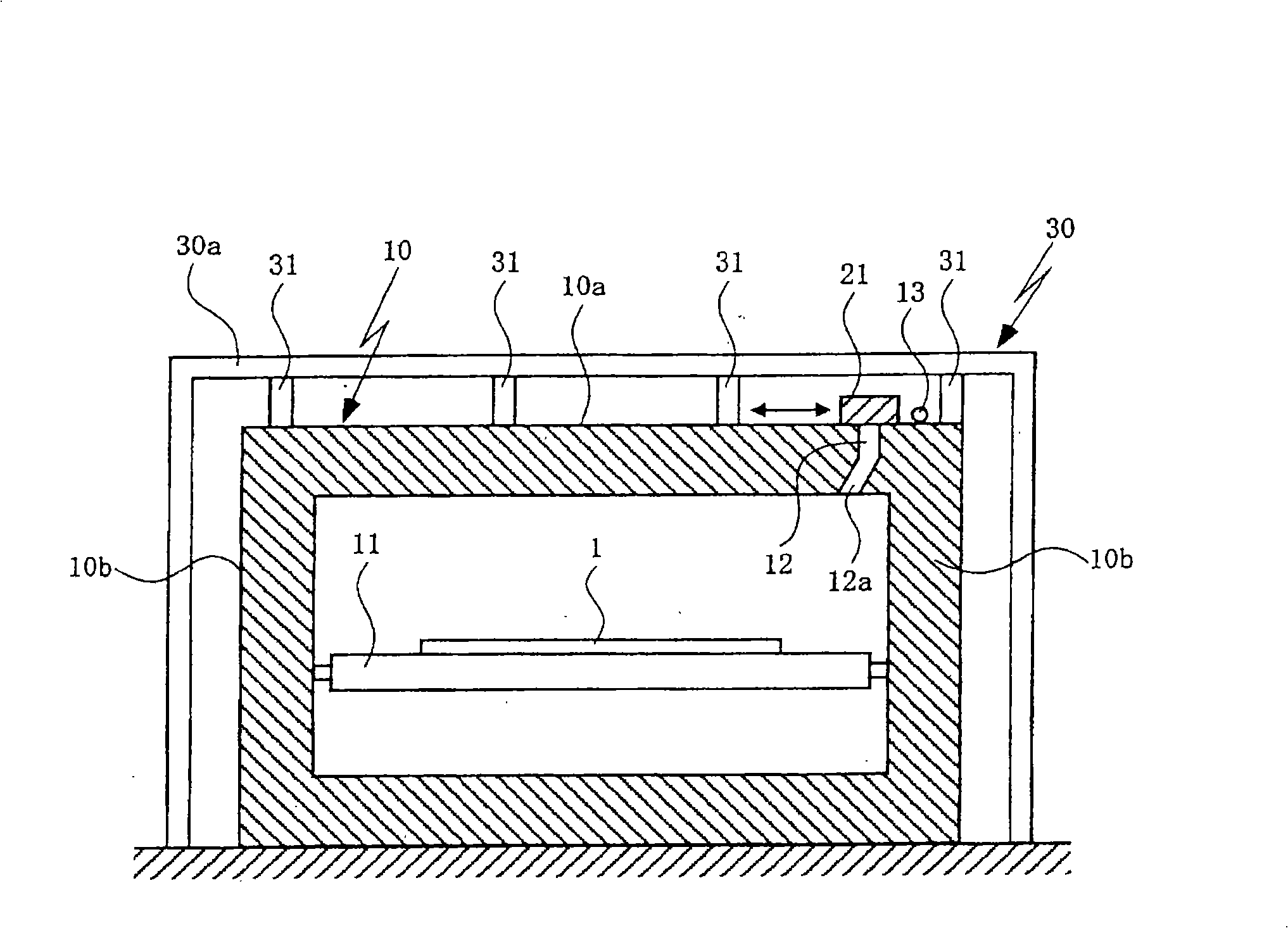
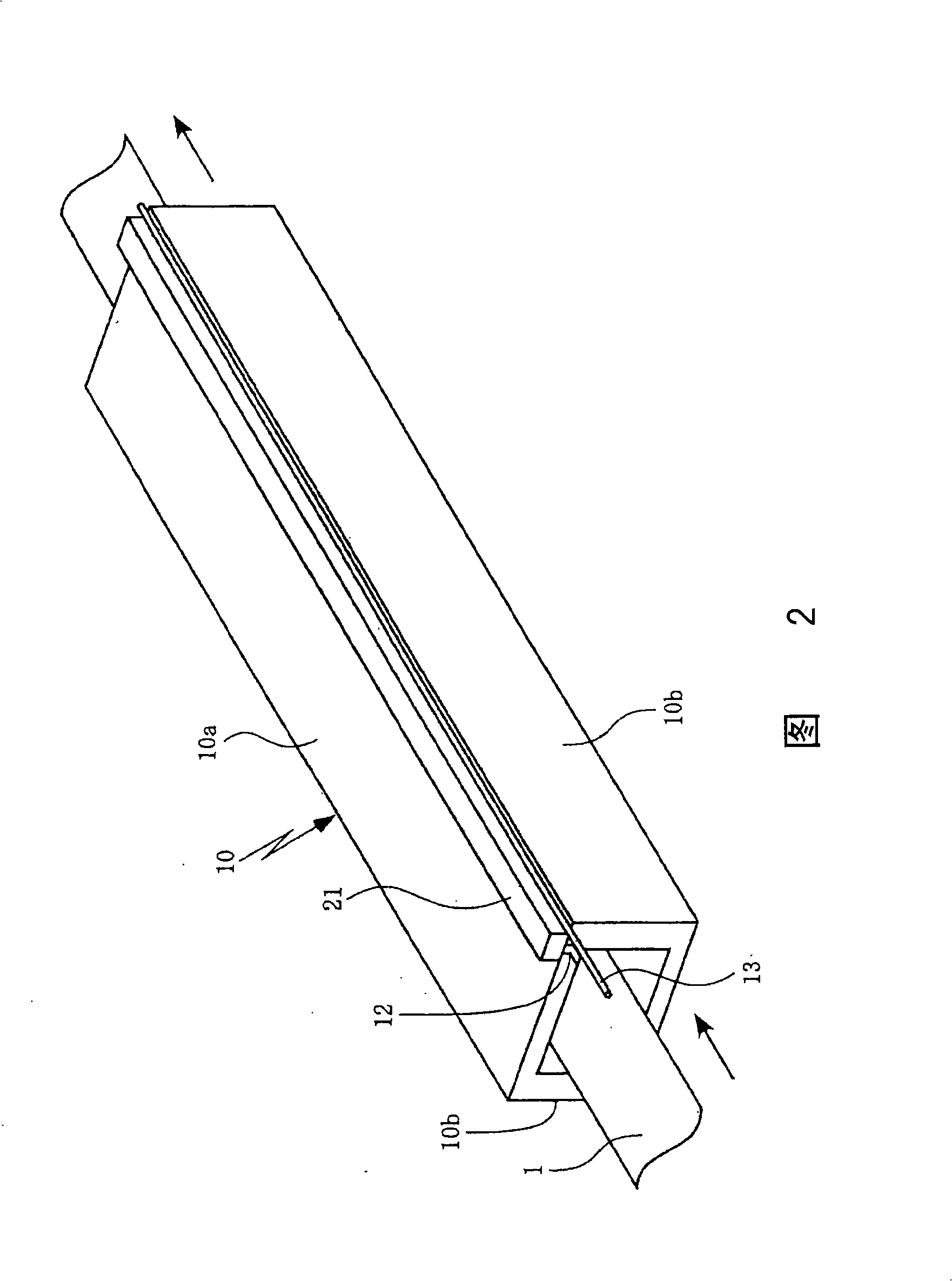
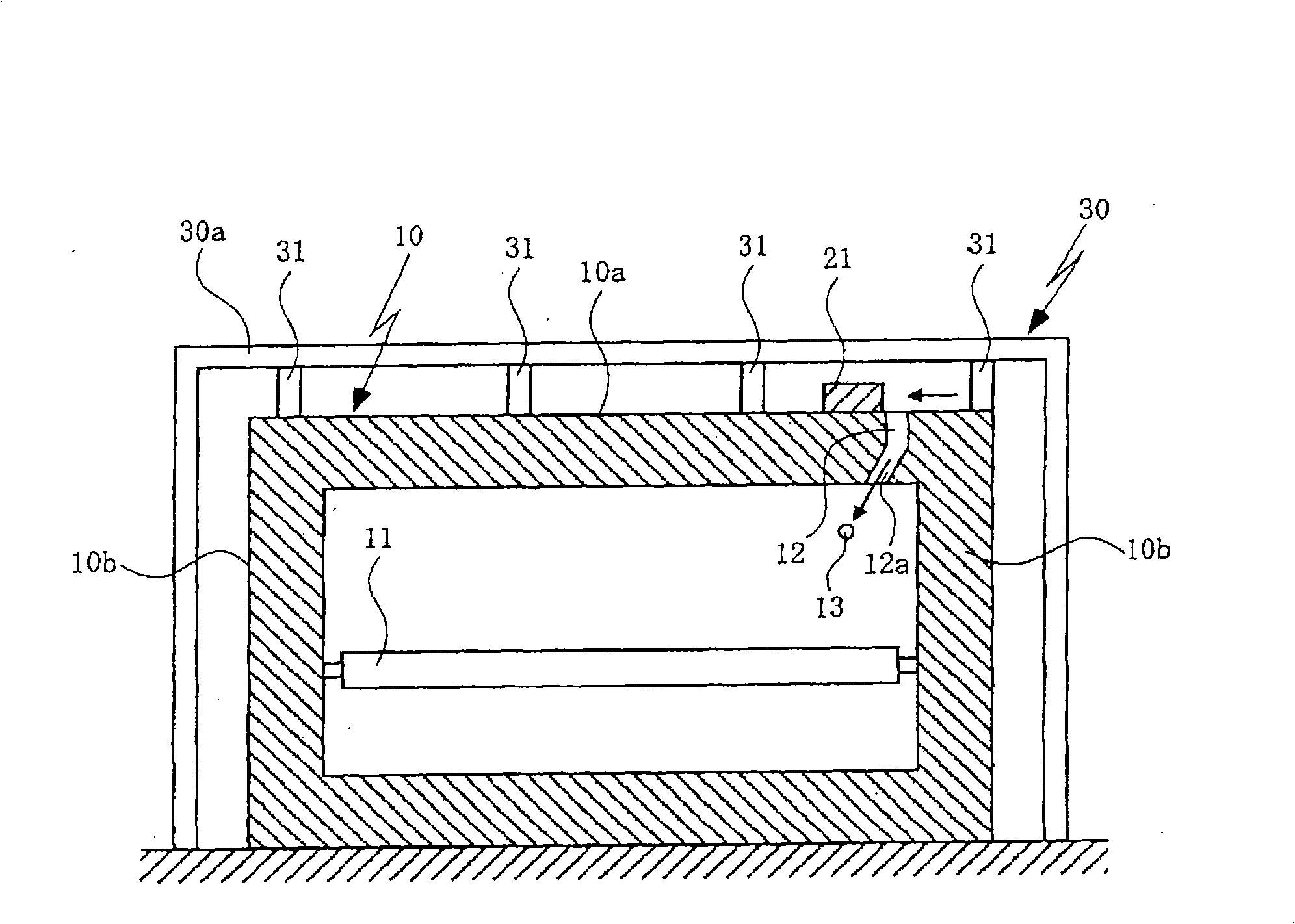
[0039] Such as figure 1As shown in Fig. 2, in the continuous annealing device of the present embodiment, a plurality of conveying rollers 11 are arranged at required intervals along the longitudinal direction in the annealing furnace 10, and the steel strip 1 to be processed is introduced from the entrance of the annealing furnace 10 In the annealing furnace 10 , the steel strip 1 is moved on the conveying rollers 11 to anneal the steel strip, and the annealed steel strip 1 is led out from the exit of the annealing furnace 10 .

[0040] Here, in the continuous annealing apparatus of the present embo...


PUM


Abstract

A continuous annealing apparatus moves the steel belt in the annealing furnace from the entrance side of the annealing furnace to the outlet side to process continuous annealing to the steel belt, a guide component is provided outside the annealing furnace along the entrance side of the annealing furnace to the outlet side for guiding the steel belt to insert through the inner side of the annealing furnace, a guide gap is provided along the entrance side to the outlet side the of the annealing furnace for leading the guide component in the annealing furnace, and a sealing arrangement is provided for sealing the guide gap.

Description

[0001] related application [0002] This application is based on Japanese Patent Application No. 266014 / 2007, the contents of which are incorporated herein by reference. technical field [0003] The present invention relates to a continuous annealing apparatus for continuously annealing a steel strip by moving a steel strip in an annealing furnace from an inlet side to an outlet side of the annealing furnace. In particular, it relates to a continuous annealing device for inserting a steel strip through an annealing furnace by using a guide member, which is characterized in that it can not only prevent the guide member from being deteriorated by heat, but also facilitate the operation of inserting the steel strip into the annealing furnace , especially when the steel strip in the annealing process breaks in the annealing furnace, it is easy to make the steel strip penetrate the inside of the annealing furnace. Background technique [0004] In the continuous annealing device ...

Claims


Application Information

Patent Timeline
Patent Type & Authority Applications(China)
IPC IPC(8): C21D9/56
CPCC21D9/562C21D9/56
Inventor 中川博夫
Owner CHUGAI RO CO LTD
Why Eureka
Try Eureka