Method for measuring large linear range data fusion by compound color ultra-resolved differential confocal

A differential confocal and data fusion technology, applied in measurement devices, instruments, optical devices, etc., can solve the problem that the axial linear measurement range is still limited without considering the system multiplicative noise interference, and achieves good linearity, Suppression and multiplicative noise interference, the effect of large linear range

Active Publication Date: 2009-04-22
NANTONG MINGGUANG ELECTRIC WIRE
View PDF3 Cites 9 Cited by
  • Summary
  • Abstract
  • Description
  • Claims
  • Application Information

AI Technical Summary

Problems solved by technology

[0005] The purpose of the present invention is to overcome the shortcomings of the existing complex-color super-resolution differential confocal measurement technology that does not consider the system multiplicative noise interference and the axial linear measurement range is still limited, and to provide a method that can retain the complex-color super-resolution d...

Method used


Image

  • Method for measuring large linear range data fusion by compound color ultra-resolved differential confocal
  • Method for measuring large linear range data fusion by compound color ultra-resolved differential confocal
  • Method for measuring large linear range data fusion by compound color ultra-resolved differential confocal

Examples


Embodiment Construction

[0024] Embodiments of the present invention will be described in detail below in conjunction with the accompanying drawings.

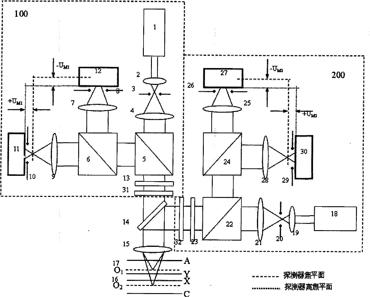
[0025] Complex color super-resolution differential confocal measurement device, such as figure 1 As shown, it includes a first super-resolution differential confocal measurement branch 100 , a second super-resolution differential confocal measurement branch 200 , a dichroic mirror 14 and a partial chromatic aberration correction objective lens 15 .

[0026] The first super-resolution differential confocal measurement branch 100 includes a first laser 1, which emits a first wavelength λ 1 The linearly polarized light is collimated by the first collimating and focusing objective lens 2, the first pinhole 3 and the first collimating and focusing objective lens 4, and then divided into two beams of polarized light by the first polarizing beam splitter 5, wherein one beam of polarized light After being split by the first beam splitter 6, one beam passes th...


PUM


Abstract

The invention relates to a method for measuring large linearity measuring range data fusion by means of compound color super resolution differential confocal measurement, belonging to the ultraprecise three-dimensional microstructure surface measuring field; firstly, formula 1 and formula 2 are utilized to respectively calculate output information of a first and a second super resolution differential confocal measuring branches, wherein, formula 3 is the actual output light intensity information of a first and a second measuring branches which are respectively obtained by adopting a compound colour super resolution differential confocal measuring device, (the formula 1, the formula 2 and the formula 3 are shown at the upper right side); Gamma1 and Gamma2 are intercepted to obtain effective output Gamma1 and Gamma2, and finally a systemic linear output fusion function (see the formula 4) is constructed and is output as the systemic final displacement response, wherein, GammaB' is a shift factor, lambda1and lambda2 are the wavelength of the first and the second measuring branches. The method remains the advantages of high space resolution and inhibiting common mode additive noise and linear range extension of the compound colour super resolution differential confocal measuring, can inhibit interference of multiplicative noise, and can obtain output characteristic curve with better linearity and larger linear measurement range.

Description

technical field [0001] The invention belongs to the field of ultra-precision three-dimensional microstructure surface measurement, and mainly relates to a large linear range data fusion method for complex color super-resolution differential confocal measurement, which is applicable to ultra-precision non-contact measurement of three-dimensional microstructure characteristics of micro-optical electromechanical components . Background technique [0002] The confocal measurement technology was first proposed by M.Minsky in 1957, and obtained the US patent in 1961, the patent number US3013467, the basic technical idea is to suppress stray light by introducing a pinhole detector, and produce axial tomography The disadvantage of this technology is that the measurement sensitivity of the axial response signal is not high near the quasi-focus area of ​​the measurement surface, so it is only suitable for defocus displacement measurement. [0003] The basic technical feature of non-t...

Claims


Application Information

Patent Timeline
IPC IPC(8): G01B11/00G01B11/02G01B11/24
Inventor 刘俭谭久彬刘涛王伟波王宇航
Owner NANTONG MINGGUANG ELECTRIC WIRE
Why Eureka
Try Eureka