Light-emitting device, white light-emitting device, illuminator, and image display

A light-emitting device and white light technology, applied in the direction of light-emitting materials, lasers, phonon exciters, etc., can solve the problems of poor color rendering, easy aging, high manufacturing cost, etc.

Active Publication Date: 2009-05-27
MITSUBISHI RAYON CO LTD
View PDF22 Cites 21 Cited by
  • Summary
  • Abstract
  • Description
  • Claims
  • Application Information

AI Technical Summary

Problems solved by technology

[0020] However, according to the prior art described in Patent Document 1, although the color rendering properties of a white light emitting device are improved by combining these phosphors, there is still a problem that all phosphors in combination exhibit a significant temperature extinction phenomenon. When the current value flowing in the white light emitting device is increased, the luminous flux emitted by the light emitting device decreases, and at the same time, a large deviation occurs in the luminous color
[0021] In addition, the red phosphor used is a sulfide-based red phosphor with low moisture resistance, so it is easy to age, and its synthesis is difficult, so its production cost is high, and the white light-emitting device obtained by using this red phosphor also has low durability. And the problem of high price
In addition, the light emission color of the green phosphor used is yellowish, so it also has the problem of insufficient light emission in the blue-green region and poor color rendering.
[0022] In addition, in the prior art described in Non-Patent Document 1 and Patent Document 2, there is a problem that sufficient luminous flux and color rendering properties cannot be obtained even by combining these phosphors, and sulfides tend to deteriorate when used in a white light emitting device. , and these phosphors are substances that obviously exhibit temperature extinction, so when the current to the white light emitting device increases, a large deviation occurs in the luminous color

Method used


Image

  • Light-emitting device, white light-emitting device, illuminator, and image display
  • Light-emitting device, white light-emitting device, illuminator, and image display
  • Light-emitting device, white light-emitting device, illuminator, and image display

Examples


Embodiment approach

[0355] The second light-emitting device of the present invention is composed of, for example, a phosphor mixture containing at least two phosphors as a wavelength conversion material and a semiconductor light-emitting device (such as a semiconductor light-emitting device such as LED or LD) that emits visible light, realizing the absorption of light emitted by the semiconductor light-emitting device. A light-emitting device that emits longer-wavelength visible light instead of visible light has high luminance, high color rendering, and less color difference with the increase or decrease of light intensity. Therefore, the second light-emitting device of the present invention having such characteristics is suitable as a light source for backlights for displays such as color liquid crystal displays and lighting devices such as surface emission.

[0356] The embodiment of the second light-emitting device of the present invention will be described in more detail below with reference ...

no. 1 approach

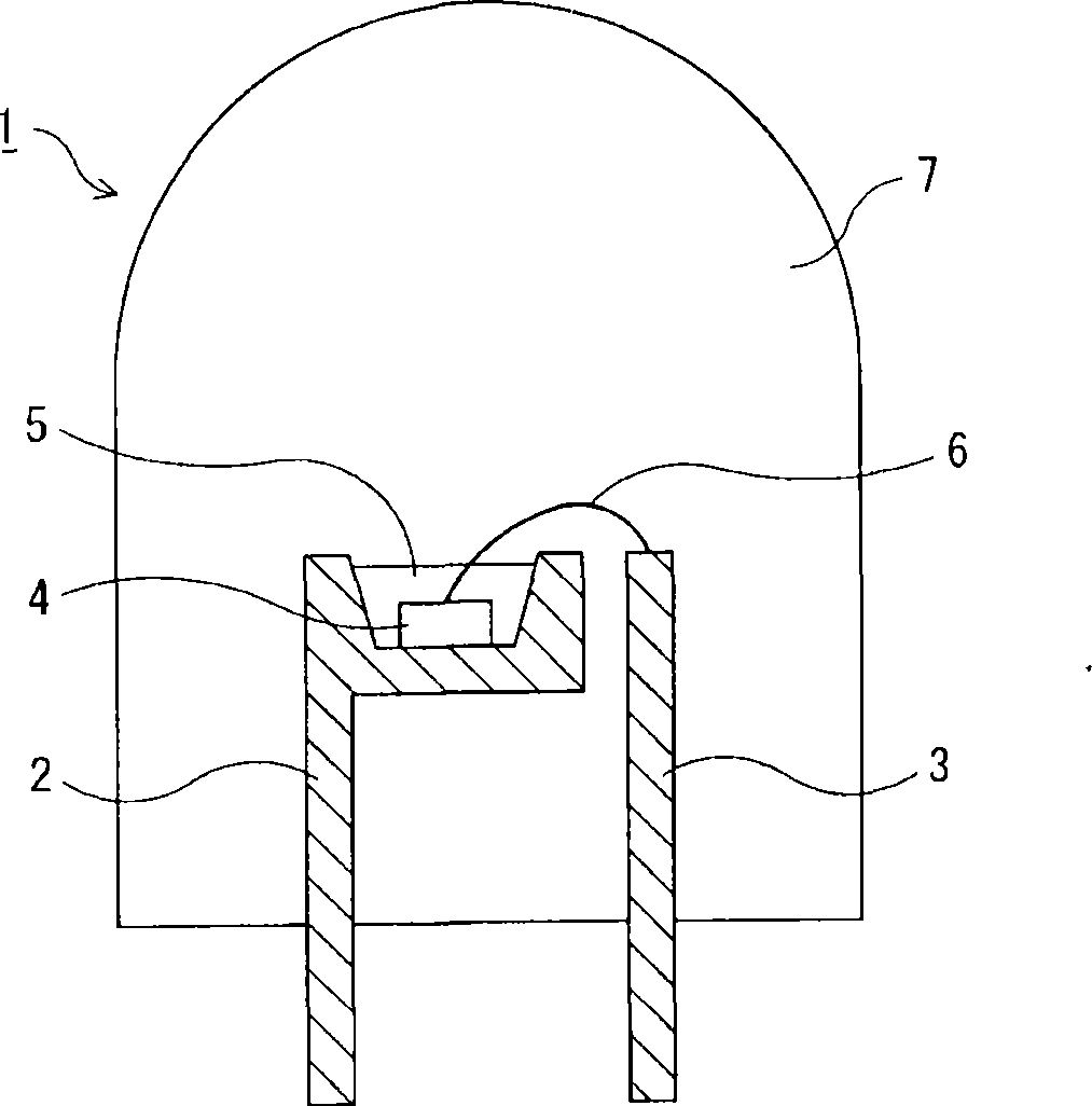
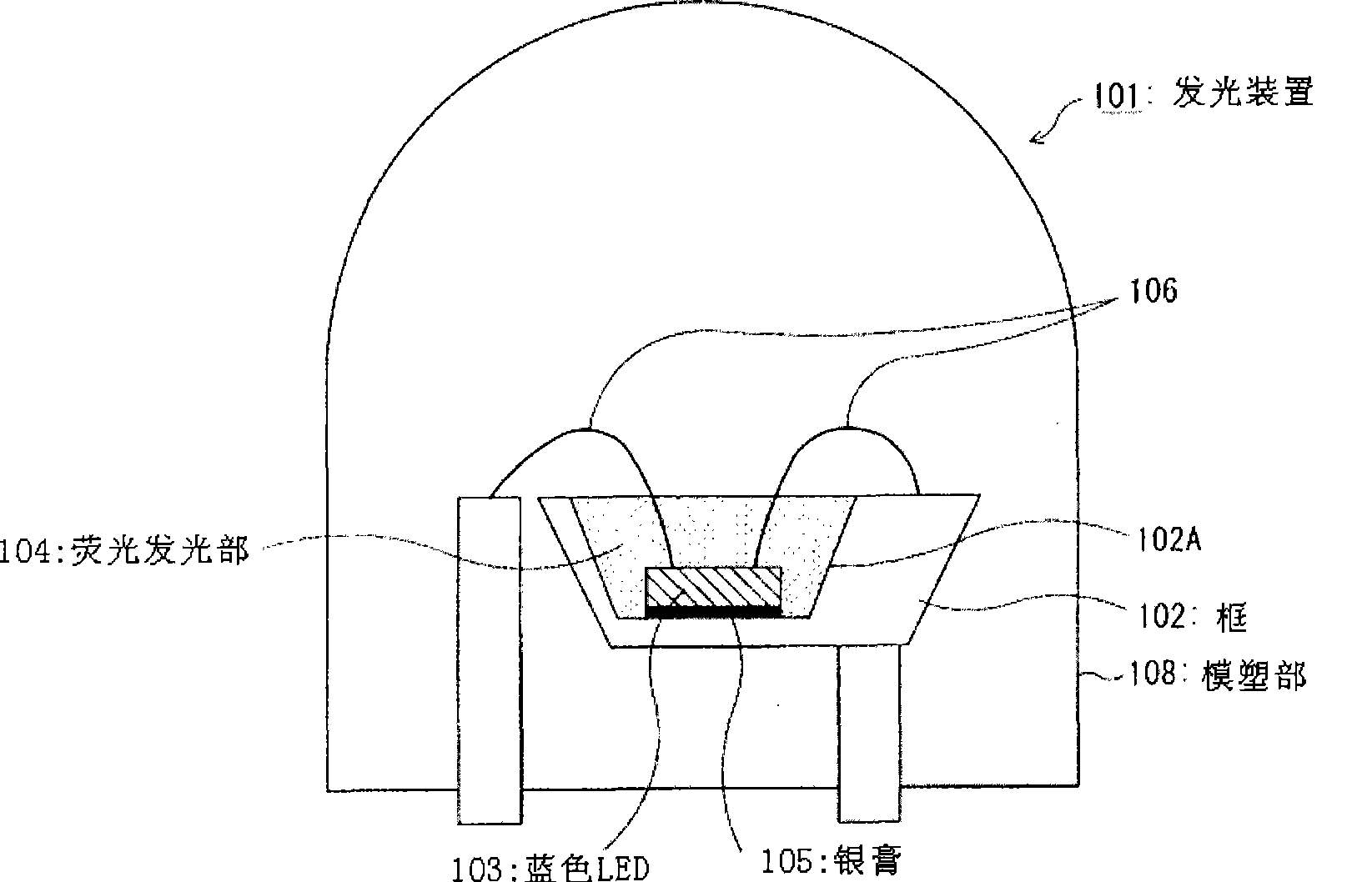
[0358] image 3 It is a diagram schematically illustrating main parts of a light-emitting device according to a first embodiment of the second light-emitting device of the present invention.

[0359] The light emitting device 101 of this embodiment mainly includes a frame 102, a blue LED (blue light emitting unit) 103 as a light source, and fluorescent light emitting light that absorbs part of the light emitted from the blue LED 103 and emits light having a different wavelength. Section 104 constitutes.

[0360] The frame 102 is a resin base for holding the blue LED 103 and the fluorescent light emitting unit 104 . On the upper surface of the frame 102, a recess (groove) 102A having a trapezoidal cross-section opening on the upper side in the figure is formed. Thus, since the frame 102 is formed into a cup shape, the light emitted from the light emitting device 101 can have directivity, and the emitted light can be effectively used.

[0361] In addition, the inner surface o...

no. 2 approach

[0368] Figure 4 It is a diagram schematically illustrating main parts of a light-emitting device that is a second embodiment of the second light-emitting device of the present invention.

[0369] The light emitting device 110 of this embodiment mainly includes a frame 112, a blue LED (blue light emitting unit) 113 as a light source, and fluorescent light emitting light that absorbs part of the light emitted from the blue LED 113 and emits light having a different wavelength. Section 114 constitutes.

[0370] The frame 112 is a resin base for holding the blue LED 113 and the fluorescent light emitting unit 114 . On the upper surface of the frame 112 is formed a concave portion (groove) 112A with a trapezoidal cross section opening on the upper side in the figure. Thus, since the frame 112 is formed into a cup shape, the light emitted from the light emitting device 110 can be given directivity, and the emitted light can be effectively used.

[0371]In addition, an unillustra...


PUM

PropertyMeasurementUnit
emission peakaaaaaaaaaa
luminous efficiencyaaaaaaaaaa
luminescence spectroscopyaaaaaaaaaa

Abstract

The invention provides a light-emitting device, a white light emitting device, an illuminating device and an image display device. The light emitted by the light-emitting device has high brightness, is closer to natural light, and has less color shift of illuminant color generated with increase and decrease of light-emitting quantity. The light-emitting device is provided with a light source emitting light by driving current and at least one wavelength-converting material which absorbs at least part of the light from the light source and emits light with a different wavelength. For the light-emitting device, the color coordinate value x1 (17.5) and the color coordinate value y1 (17.5) of the light emitted at a driving current density of 17.5A / cm<2> , and the color coordinate value x1 (70) and the color coordinate value y1 (70) of the light emitted at a driving current density of 70A / cm<2> satisfy the following expressions (D) and (E): in expression (D), x1 (17.5) - x1 (70) is equal to or more than -0.06, and equal to or less than 0.06; in expression (E), y1 (17.5) - y1 (70) is equal to or more than -0.06, and equal to or less than 0.06; in expression (E).

Description

[0001] This application is a divisional application, the application number of the original application is 200680008622.2, the filing date is March 17, 2006, and the title of the invention is "light emitting device, white light emitting device, lighting device and image display device". technical field [0002] The present invention relates to a light emitting device, a white light emitting device, and an illuminating device and an image display device using the above device. In particular, it relates to a light emitting device and a white light emitting device that combine a light source such as a light emitting diode (LED) or a laser diode (LD) with a wavelength conversion material such as a phosphor that absorbs light emitted from the light source and emits light of a different wavelength. , and an illumination device and an image display device using the above device. Background technique [0003] Conventionally, it is known that a white light-emitting light-emitting dev...

Claims


Application Information

Patent Timeline
Patent Type & Authority Applications(China)
IPC IPC(8): H01L33/00H01S5/00C09K11/79C09K11/80
Inventor 木岛直人下村康夫金田英明竹下公也
Owner MITSUBISHI RAYON CO LTD
Why Eureka
Try Eureka