
Image blur correction device and imaging apparatus equipped therewith

A blur correction, image technology, applied in the field of image blur correction devices, can solve the problems of imaging performance degradation, aberration or focus shift increase, etc., to achieve the effect of eliminating loose fit

Inactive Publication Date: 2011-05-11
RICOH KK
View PDF9 Cites 0 Cited by
  • Summary
  • Abstract
  • Description
  • Claims
  • Application Information

AI Technical Summary

Problems solved by technology

Moreover, the imaging device has a problem that the loose fit tilts the lens or the imaging element, resulting in an increase in aberration or focus shift, thereby degrading the imaging performance

Method used


Image

  • Image blur correction device and imaging apparatus equipped therewith
  • Image blur correction device and imaging apparatus equipped therewith
  • Image blur correction device and imaging apparatus equipped therewith

Examples


Embodiment Construction

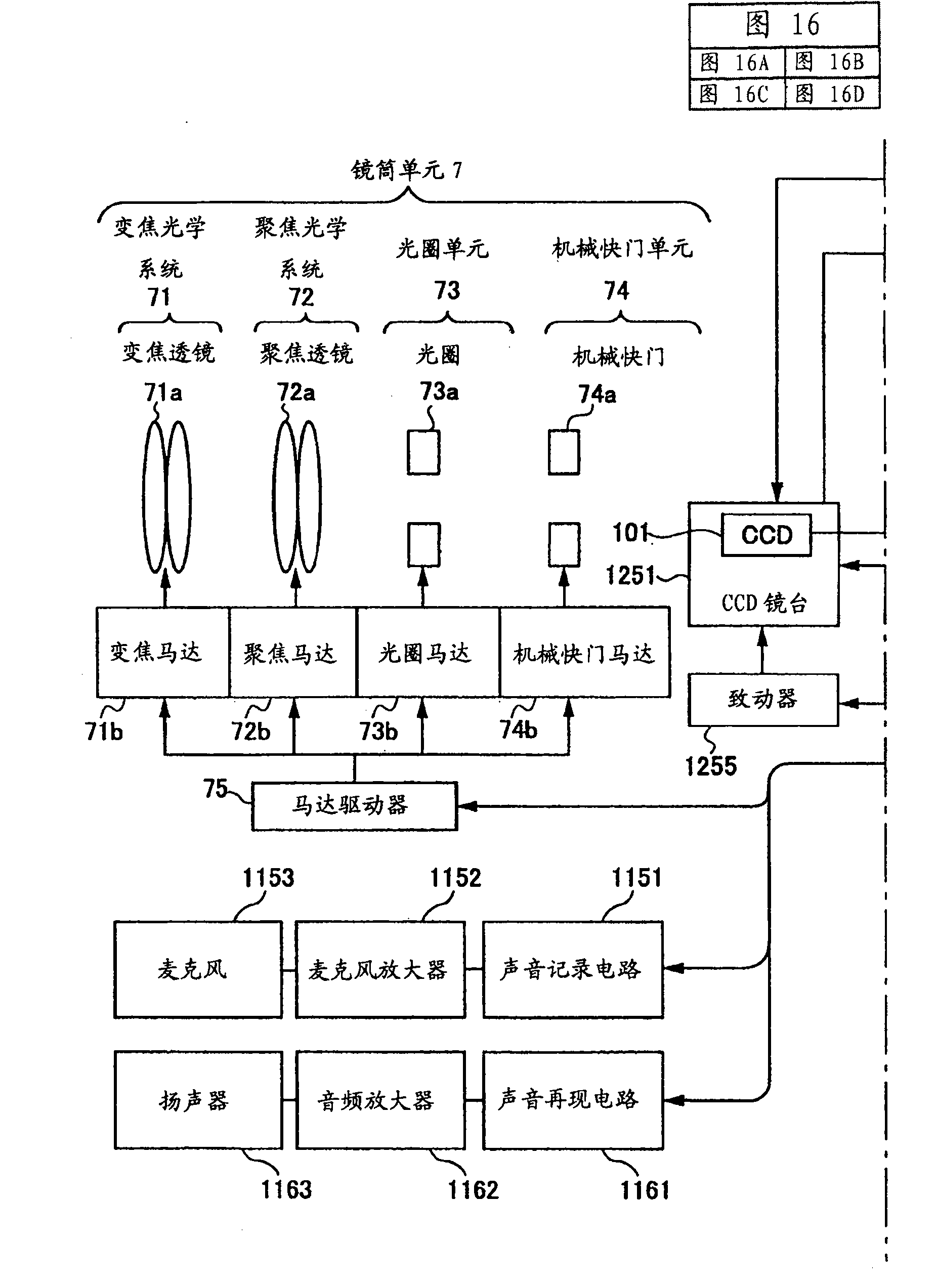
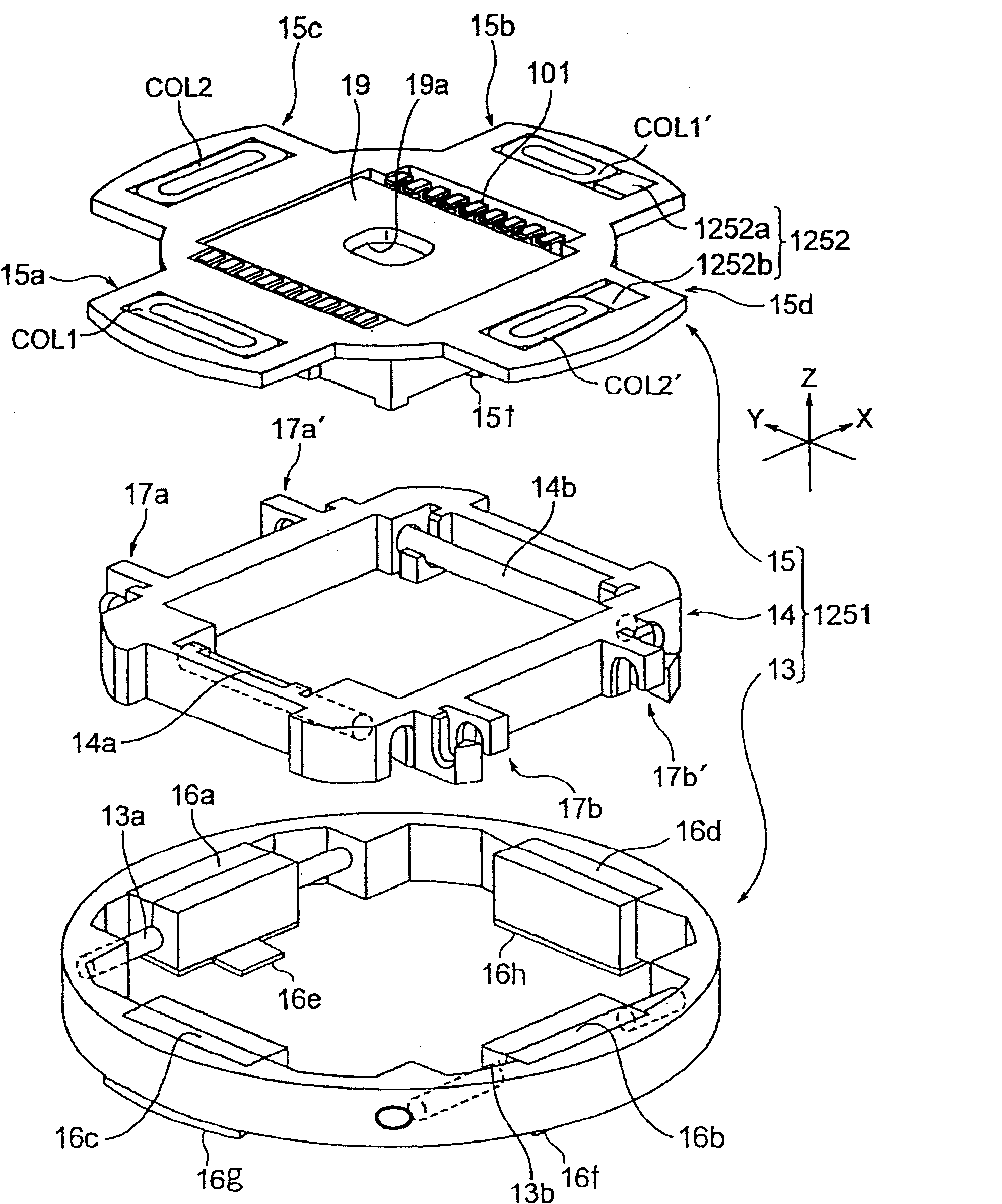
[0112] Embodiments of the image blur correction device of the present invention and an imaging apparatus provided with the device will be described with reference to the drawings. However, the present invention is not limited only to the embodiments described below.

[0113] A first embodiment of the image blur correction device of the present invention will be described below.

[0114] The first embodiment of the image blur correction device of the present invention is an image blur correction device, comprising: a movable frame, which is provided with a lens or an imaging element and has a guide part; a fixed frame with a guide support part, the A guide support portion movably supports the movable frame by being in contact with the guide portion; and a drive mechanism that drives the movable frame by moving the movable frame relative to the fixed frame for correcting image blur. The fixed frame has a magnetic body, and the movable frame has a push magnet at a position corre...


PUM


Abstract

An image blur correction device includes: a movable frame which is equipped with a lens or an imaging element and has a guide part; a fixed frame having a guide supporting part which movably supports the movable frame by coming into contact with the guide part; and a drive mechanism which drives the movable frame for correcting image blur by moving the movable frame relative to the fixed frame. The fixed frame has magnetic bodies, and the movable frame has urging magnets at positions corresponding to the magnetic bodies. Specifically, the urging magnets use attractive force between the magnets and the magnetic bodies, so as to urge the movable frame in a direction in which the guide part and the guide supporting part come into contact with each other.

Description

[0001] priority [0002] This application is based on and claims priority from each of Japanese Patent Application Nos. 2006-226290 filed on August 23, 2006 and 2006-226291 filed on August 23, 2006, and the entire contents thereof are hereby incorporated by reference Come in. technical field [0003] The present invention relates to an image blur correction device that corrects image blur when an image of an object is captured by allowing the image of the object to be imaged on an imaging element that generates image data to form an image of the object, and also relates to an imaging device . More particularly, the present invention relates to an image blur correction device having an image blur correction function capable of capturing a blur-corrected object image by allowing an imaging element to follow movement of the object image due to camera shake, and also relates to a device provided with the An imaging device of an image blur correction device. Background techniqu...

Claims


Application Information

Patent Timeline
Patent Type & Authority Patents(China)
IPC IPC(8): G03B5/00
Inventor 大野武英
Owner RICOH KK
Learn More