Surface-emitting laser array, optical scanning device, and image forming device

一种激光器阵列、表面发射的技术,应用在激光器、半导体激光器、光学等方向,能够解决激光器输出性能降低、可靠性下降等问题

Active Publication Date: 2009-09-23
RICOH KK
View PDF4 Cites 6 Cited by
  • Summary
  • Abstract
  • Description
  • Claims
  • Application Information

AI Technical Summary

Problems solved by technology

[0010] The surface emitting laser array according to the prior art has such a problem that if the interval between two light emitting parts is shortened, the laser output performance is lowered or the reliability is lowered due to the influence of heat generated in other light emitting parts.

Method used


Image

  • Surface-emitting laser array, optical scanning device, and image forming device
  • Surface-emitting laser array, optical scanning device, and image forming device
  • Surface-emitting laser array, optical scanning device, and image forming device

Examples


Embodiment Construction

[0041] Various embodiments of the present invention will be described below with reference to these drawings.

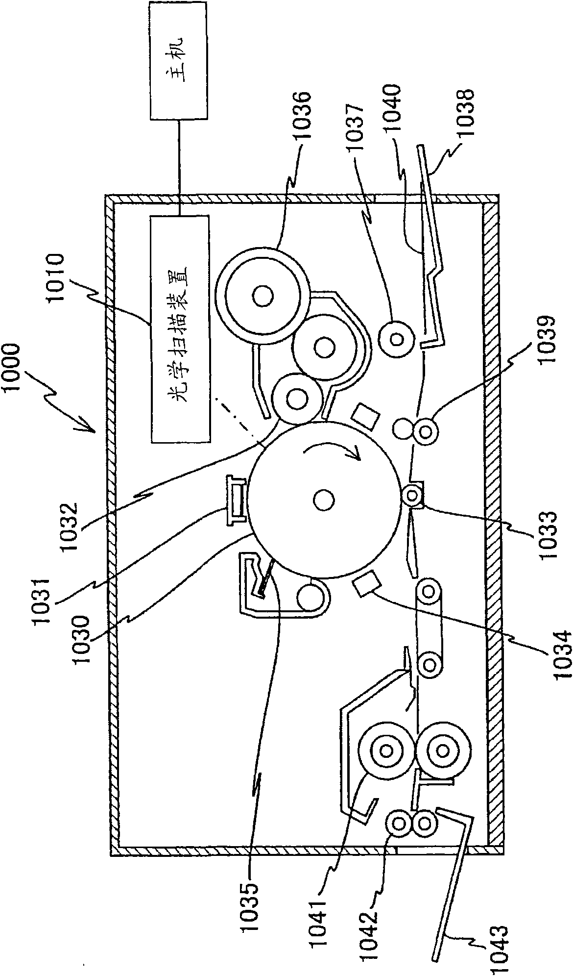
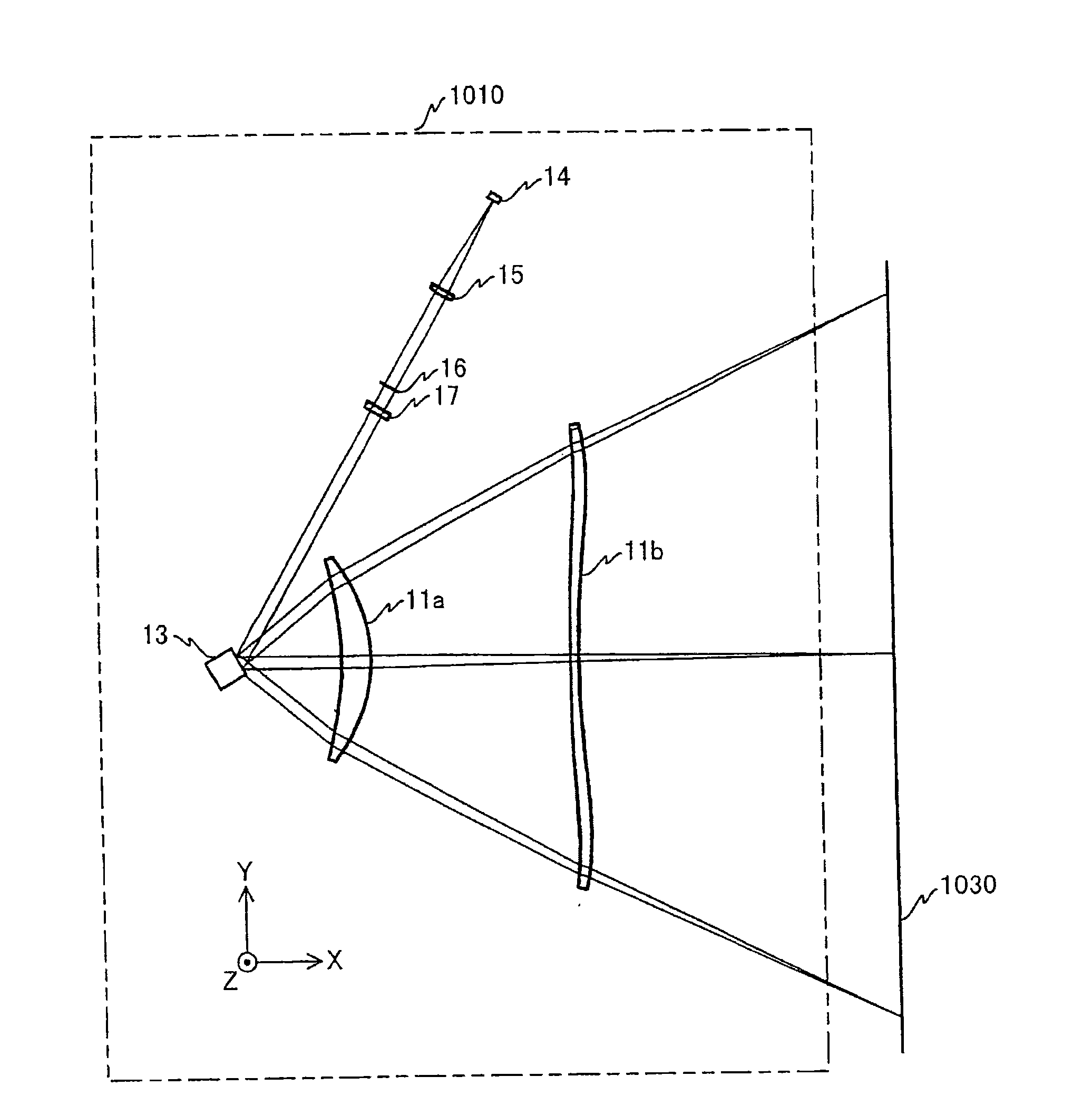
[0042] figure 1 The structure of a laser printer 1000 as an image forming apparatus in the embodiment of the present invention is shown. This laser printer 1000 includes an optical scanning device 1010, a photosensitive drum 1030, a charging device 1031, a developing roller 1032, a transfer charging device 1033, a discharging device 1034, a cleaning blade 1035, a toner cartridge 1036, a paper feeding roller 1037, a paper feeding Tray 1038 , Registration Roller Pair 1039 , Fixing Roller 1041 , Paper Out Roller 1042 , and Paper Out Tray 1043 .

[0043] A photosensitive layer is formed on the surface of the photosensitive drum 1030 . The surface of the photosensitive drum 1030 is the surface to be scanned. In this embodiment, the photosensitive drum 1032 is formed along the figure 1 Turn in the direction indicated by the arrow.

[0044] A charging device 1031 , a d...


PUM


Abstract

The present invention provides a surface- emitting laser array, an optical scanning device and an image forming device. The surface-emitting laser array includes a plurality of light emitting parts arranged in a two-dimensional formation having two orthogonal directions. When the plurality of light emitting parts are orthogonally projected on a virtual line parallel to one of the two orthogonal directions, a spacing between two of the plurality of light emitting parts along the virtual line is equal to an integral multiple of a predetermined value. The plurality of light emitting parts include a first light emitting part, a second light emitting part adjacent to the first light emitting part, and a third light emitting part adjacent to the second light emitting part, and a spacing between the first and second light emitting parts differs from a spacing between the second and third light emitting parts.

Description

technical field [0001] The present invention relates to a surface-emitting laser array in which surface-emitting laser elements are arranged two-dimensionally, an optical scanning device including the surface-emitting laser array, and an imaging apparatus including the surface-emitting laser array. Background technique [0002] In electrophotographic imaging, an imaging method using a laser beam is widely used in order to obtain high-density image quality. In electrophotographic image forming, a method of forming an electrophotographic latent image on a photosensitive drum is generally adopted in that a laser beam output from a polygon mirror is aligned along the axial direction of the photosensitive drum while the photosensitive drum is rotating (sub-scanning). The surface of the photosensitive drum is optically scanned (main scan). [0003] In this electrophotographic imaging, high-speed formation of high-density images is required. If the image resolution is doubled for...

Claims


Application Information

Patent Timeline
Patent Type & Authority Applications(China)
IPC IPC(8): H01S5/18B41J2/44B41J2/45B41J2/455G02B26/10G03G15/04H04N1/113
CPCB41J2/45G03G2215/0404H04N1/121H04N1/113H04N1/0311B41J2/473G03G15/326H04N2201/03104G03G15/04036G02B26/123G03G2215/0421H01S5/423H04N1/1135H04N1/195H04N1/19515B41J2/455G03G15/04072G03G15/0435H01S5/183
Inventor 佐藤俊一林善纪市井大辅
Owner RICOH KK
Why Eureka
Try Eureka