Back electrode strap for thin film solar cell and producing method of thin film solar cell

A technology for solar cells and back electrodes, which is applied in the direction of final product manufacturing, sustainable manufacturing/processing, circuits, etc., can solve the problems of increasing the number of manufacturing processes of thin-film solar cells, and achieve simplification of manufacturing processes, efficiency of manufacturing processes, The effect of easy manufacturing

Inactive Publication Date: 2012-07-04
MITSUBISHI MATERIALS CORP
View PDF6 Cites 1 Cited by
  • Summary
  • Abstract
  • Description
  • Claims
  • Application Information

AI Technical Summary

Problems solved by technology

However, even according to the above-mentioned wet coating method, the composition for a transparent conductive film and the composition for a conductive reflective film are applied or cured directly on the photoelectric conversion layer, thereby resulting in a number of manufacturing steps for thin-film solar cells. increase, so it is desired to shorten, simplify, and improve the number of manufacturing steps

Method used


Image

  • Back electrode strap for thin film solar cell and producing method of thin film solar cell
  • Back electrode strap for thin film solar cell and producing method of thin film solar cell
  • Back electrode strap for thin film solar cell and producing method of thin film solar cell

Examples


Embodiment 1

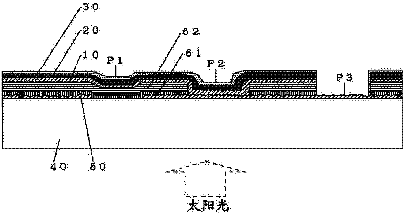
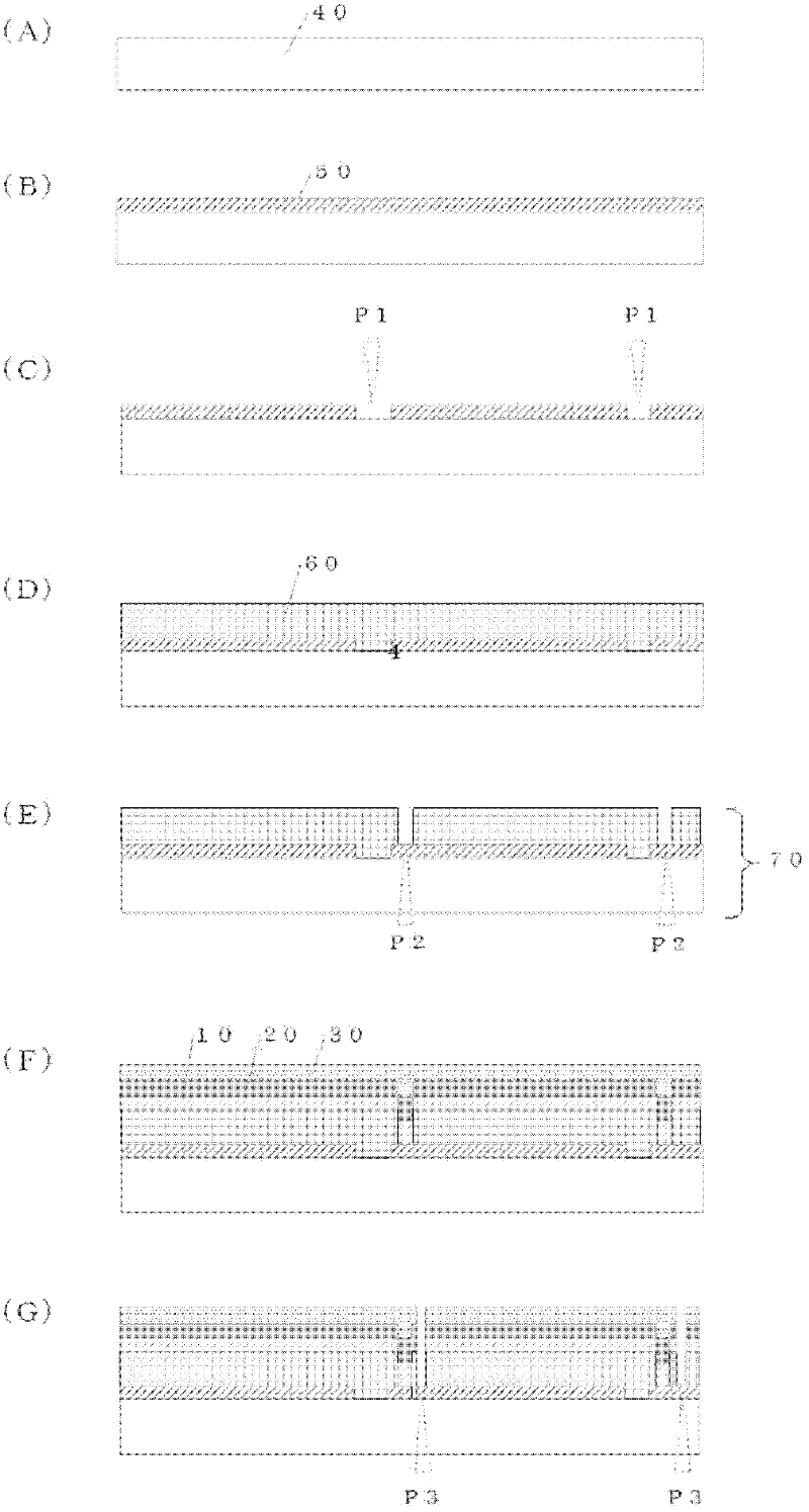
[0127] use figure 2 (A)~(E) explain the method of manufacturing the adherend, and use it in the subsequent steps Figure 5 Be explained. First, like figure 2 As shown in (B), the transparent substrate 40 prepares a glass plate with a length of 10 cm square and a thickness of 4 mm, and SnO is used as the transparent conductive film 50 2 . At this time, the film thickness of the transparent conductive film 50 is 800 nm, the sheet resistance is 10 Ω / □, and the haze is 15 to 20%.

[0128] Then, like figure 2 As shown in (C), an amorphous silicon layer 61 is formed with a thickness of 300 nm from the transparent conductive film 50 processed to the laser scribing P1 by the plasma CVD method, and then the amorphous silicon layer 61 is deposited by the plasma CVD method A microcrystalline silicon layer 62 is formed with a thickness of 1.7 μm, thereby forming figure 2 The silicon-based photoelectric conversion layer 60 shown in (D). Such as figure 2 As shown in (E), the photoelectr...

Embodiment 2~23

[0133] Except for setting the conditions shown in Table 1, the test was performed in the same manner as in Example 1. Here, the silica sol-gel used in Example 2 and the like used SB-10A manufactured by Mitsubishi MATERIAL. In addition, the reflective electrode film composition used in the wet coating method of Example 12 and the like was produced as follows.

[0134] First, silver nitrate is dissolved in deionized water to prepare a metal ion aqueous solution. Then, sodium citrate was dissolved in deionized water to prepare an aqueous sodium citrate solution having a concentration of 26% by mass. In a nitrogen gas stream maintained at 35°C, granular ferrous sulfate was directly added to the sodium citrate aqueous solution and dissolved to prepare a reducing agent aqueous solution containing citrate ions and ferrous ions in a molar ratio of 3:2. Next, while maintaining the above-mentioned nitrogen gas flow at 35°C, the stir bar of the magnetic stirrer was put into the reducing a...

Embodiment 24

[0139] use Figure 5 Be explained. Figure 5 As for the adherend 7 shown in (a), the adherend produced in Example 1 was used. Next, a carrier tape 8a made of polyethylene terephthalate (PET) was coated with a silica sol-gel as a barrier film 3a so that the film thickness after heat treatment became 1 μm using a mold coating device, and Heat treatment at 120°C for 10 minutes. On this basis, an 800 nm Ag film was formed by sputtering as the reflective electrode film 2a.

[0140] Next, the transparent electrode film composition used when forming the transparent electrode film 1a is prepared as follows. As the conductive fine particles, 50 parts by mass of AZO powder having an atomic ratio of Al / (Al+Zn)=0.02 and a particle size of 0.03 μm was added, and IPA was added as a dispersion medium to make the entirety 100 parts by mass. A horizontal mill (horizontal bead mill) was operated on the mixture using zirconia beads with a diameter of 0.3 mm for 2 hours to disperse the fine part...


PUM


Abstract

The invention relates to a back electrode strap for a thin film solar cell and a producing method of a thin film solar cell. The invention aims to simplify and improve efficiency of the processing of the back electrode strap for a thin film solar cell, and further save a part of laser drawing process used in the production of common thin film solar cells, and speed up the producing process of thin film solar cells. Transparent electrode thin films and reflective electrode thin films are laminated, and the transparent electrode thin films have adhesiveness. Preferably the back electrode strap for the thin film solar cell of a barrier layer is further laminated at the side of the reflective electrode thin film.

Description

Technical field [0001] The invention relates to a back electrode tape for thin film solar cells and a method for manufacturing a thin film solar cell using the back electrode tape. More specifically, it relates to a thin-film solar cell back electrode tape that can manufacture a thin-film solar cell by a simple manufacturing method, and can effectively use incident sunlight to improve the power generation efficiency of the thin-film solar cell. Background technique [0002] At present, from the standpoint of environmental protection, the research and development and practical application of green energy are being promoted. Solar cells are attracting attention in terms of inexhaustible and pollution-free sunlight as energy. In the past, solar cells have been using monocrystalline silicon or polycrystalline silicon bulk solar cells. However, due to the high manufacturing cost and low productivity of bulk solar cells, there is an urgent need to develop solar cells that save as much ...

Claims


Application Information

Patent Timeline
Patent Type & Authority Applications(China)
IPC IPC(8): H01L31/0224H01L31/20
CPCY02P70/50
Inventor 米泽岳洋马渡芙弓山崎和彦
Owner MITSUBISHI MATERIALS CORP
Why Eureka
Try Eureka