Film heating/molding device of blister packaging machine

A blister packaging machine and thermoforming technology, used in packaging, transportation and packaging, multiple packages, etc., can solve the problems of easy deformation of pockets and poor work efficiency, improve thermal conductivity, reduce deviation, and prevent leakage. Effect

Active Publication Date: 2020-12-04
妙一公司
View PDF8 Cites 0 Cited by
  • Summary
  • Abstract
  • Description
  • Claims
  • Application Information

AI Technical Summary

Problems solved by technology

[0004] Therefore, in order to form a part of the heated film into a desired groove shape, a PVC film is suitable, but since the entire surface of the PVC film is heated and formed, the film forming the groove is more difficult than other parts. Thick, especially the thickness of the sheet at the top of the pocket becomes extremely thin. Therefore, after filling it with tablets, make the pockets of the two films face each other and overlap the films so that the pockets cross each other. On the other hand, when packaging or selling, there is a problem that the pocket is easily deformed.
[0005] In addition, although the polypropylene film is also used to form the blister sheet, the polypropylene film sheet is the same as the PVC film sheet, compared with other parts, the film thickness of the forming pocket, especially the top surface of the pocket The thickness of the sheet at the position becomes extremely thin, and there is a problem that the pocket is easily deformed after the tablet is filled.
Moreover, if the entire surface of the polypropylene film sheet is heated and molded, the thermal shrinkage ratio of the polypropylene film sheet and the aluminum film will be different, and the blister sheet after tablet filling will be warped. When the sheets are stacked and packaged with their faces facing each other, they cannot be automatically stacked by a machine, and have to be done manually by the operator, which has the problem of poor work efficiency.

Method used


Image

  • Film heating/molding device of blister packaging machine
  • Film heating/molding device of blister packaging machine
  • Film heating/molding device of blister packaging machine

Examples


Embodiment Construction

[0028] Hereinafter, embodiment of the thermoforming apparatus of the film in the blister packaging machine of this invention is demonstrated based on drawing.

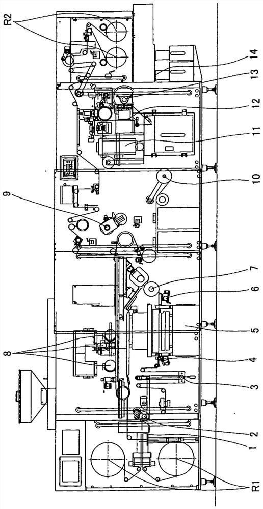
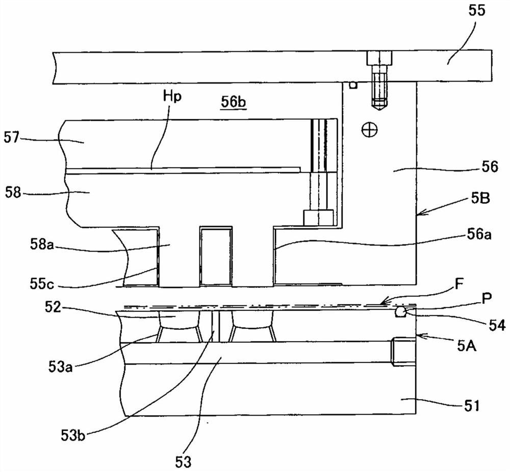
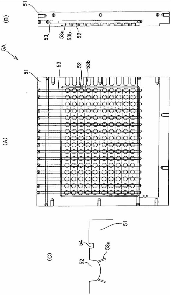
[0029] Figure 1 ~ Figure 3 An example of the film thermoforming device of the blister packaging machine of the present invention is shown.

[0030] The blister packaging machine as figure 1 As shown, the film F that is sequentially released from the film roll R1 formed by winding a film F such as a polypropylene film passes through the film connecting device 1 and is released by the discharge roller 2. After the tension is adjusted by the constant tension roller 3, it is released by the guide roller 4. It is intermittently supplied to the next thermoforming device 5. Here, after forming the required pockets, the tablets are supplied to each pocket by the tablet supplying device 8 via the guide roller 6 and the forming film conveying roller 7. After tableting, the aluminum film roll R2 formed by winding the sheet-sh...


PUM


Abstract

In order to provide a film heating / molding device of a blister packaging machine with which it is possible to perform molding without extreme reduction in the sheet thickness of a pocket upper-surfaceportion, adopt a configuration of superposition without warping, and conduct stable molding at high speed, the present invention is configured so that a compressed-air injection mechanism disposed ona mold (5A) side comprises a compressed-air injection hole (53a) that opens in the inner bottom part of a pocket hole (52) in the mold (5A), and a compressed-air injection hole (53b) that opens in the periphery of the pocket hole (52) in the mold (5A).

Description

technical field [0001] The invention relates to a film heating forming method of a blister packaging machine. Background technique [0002] Conventionally, in a blister pack for packaging tablets such as medicines using a film such as a PVC film, a long film that is released continuously intermittently is sandwiched between a flat plate that is arranged facing each other and moves in the contact / separation direction. Heating the space between the discs and performing desired heating, using a molding die to form pockets for accommodating one or more tablets on the heat-softened film, and then supplying tablets to each pocket, by having the pocket The aluminum film is attached to the film to seal the pockets, and a sheet is cut in such a way that the desired number of pockets are present to form a product. [0003] In addition, the forming of the film in the above-mentioned conventional blister packaging machine generally utilizes a roll formed by winding a sheet-shaped PVC f...

Claims


Application Information

Patent Timeline
Patent Type & Authority Applications(China)
IPC IPC(8): B65B47/08B29C51/10B29C51/42B65B11/52B65B47/02
CPCB65B47/08B29C51/42B29C51/08B29C51/10B65B47/02B65B9/045B65B11/52
Inventor 小鲷健池内健介
Owner 妙一公司
Why Eureka
Try Eureka